Use this DDTCCRUB 4S-2A Battery Charger Module Step Up Boost Li-Polymer
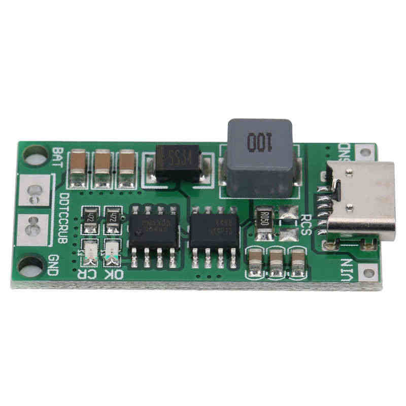
Change the RCS resistor from 50mOhm to 125mOhm (0.125 Ohm) to change the charging current to 300mA.
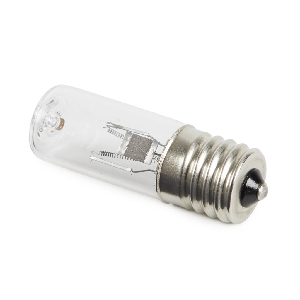
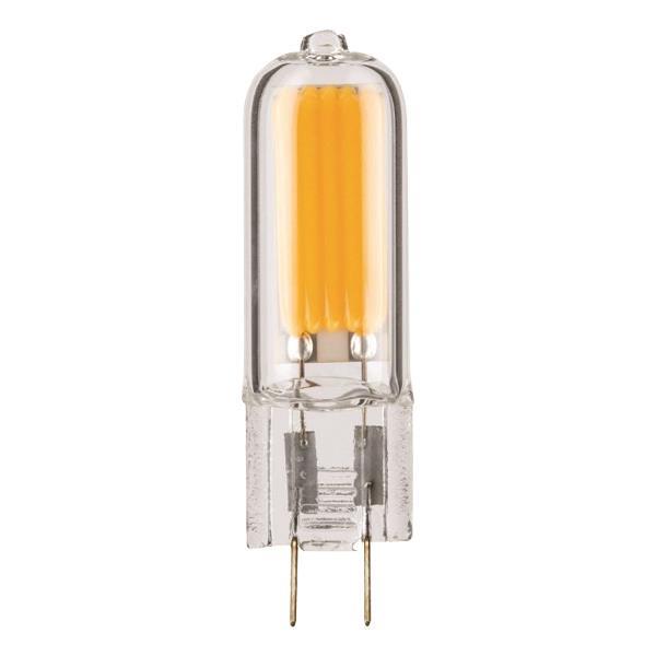
Remember, these bulb have to be supplied 16V (min) so the filament starts glowing, but once the arc is established, current has to be limited to 300mA (settling at around 10V)
Don’t let it run more than few sec on the front of your naked eye/skin.
]]>Use this DDTCCRUB 4S-2A Battery Charger Module Step Up Boost Li-Polymer
Change the RCS resistor from 50mOhm to 125mOhm (0.125 Ohm) to change the charging current to 300mA.
Remember, these bulb have to be supplied 16V (min) so the filament starts glowing, but once the arc is established, current has to be limited to 300mA (settling at around 10V)
Don’t let it run more than few sec on the front of your naked eye/skin.
]]>But after having listened it quite few times the original sound track, I quickly realize there is something wrong, not the loudness war, something worst: noise pickup during recording, not filtered out during mixing.
Almost the complete album is tainted, for example, in this track, “Message from Home”, is a single piano recording showing this noise standing out clearely.
Dont get me started it’s because of the MP3 or format artifact, this is present on any version, MP3, FLAC, and even on Spotify online!
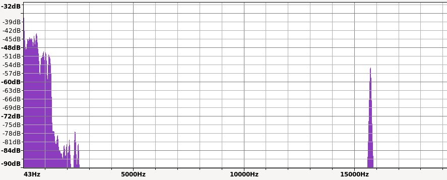
Here is an extract of this sound track, do you hear it? It hurts!
If you cannot hear sounds around 16Khz, no problem, here pitched down version, to 0.5 with the noise is now at 8Khz if you don’t hear it, you may want to consult a specialist.
Because it may sound crazy that a multi million dollar movie, OST and sound track composer (Hans Zimmer) get away with this, I’ve looked up and found this reddit thread mentioning it:
Well, I’m not crazy after all and it look like it’s a Pilot Signal at “15.7342657 kHz is used to indicate the presence of MTS stereo.”
So that’s it, there is nothing to do, we are stuck with this (at least I can filter out my own version), but please, mixing engineers, next time, pay attention.
But after having listened it quite few times the original sound track, I quickly realize there is something wrong, not the loudness war, something worst: noise pickup during recording, not filtered out during mixing.
Almost the complete album is tainted, for example, in this track, “Message from Home”, is a single piano recording showing this noise standing out clearely.
Dont get me started it’s because of the MP3 or format artifact, this is present on any version, MP3, FLAC, and even on Spotify online!
Here is an extract of this sound track, do you hear it? It hurts!
If you cannot hear sounds around 16Khz, no problem, here pitched down version, to 0.5 with the noise is now at 8Khz if you don’t hear it, you may want to consult a specialist.
Because it may sound crazy that a multi million dollar movie, OST and sound track composer (Hans Zimmer) get away with this, I’ve looked up and found this reddit thread mentioning it:
Well, I’m not crazy after all and it look like it’s a Pilot Signal at “15.7342657 kHz is used to indicate the presence of MTS stereo.”
So that’s it, there is nothing to do, we are stuck with this (at least I can filter out my own version), but please, mixing engineers, next time, pay attention.
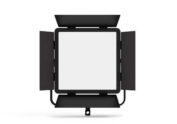
After fixing a TV with LED backlight, let’s dive in different performance of light fixture/light bulbs.
This effect is especially present in LED light fixtures where there is no inertia: incandescent or fluorescent light have a thermal or phosphor inertia and continue to glow a flick of second after the power is cut. But not the LED (even though there is some phosphor in them), this leads to have a close relation of the light intensity and the supply voltage.
Most of LED light bulb are supplied from main, the quality of the AC/DC converter takes a main role here. Because good rectification and filtering cost, manufacturer are cutting them, and you get this effect.
You can find two type of power supply on LED bulbs: simple rectification with LED string to match the AC rectified voltage. Or AC/DC converter with inductor and constant current control (this is what you want).
I wanted to “quantify” it, more that just a feeling, but didn’t want to drop hard cash (k€$ range) for dedicated equipment.
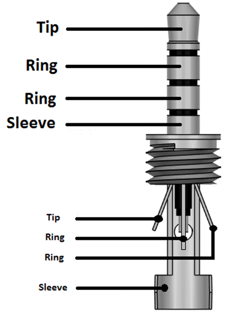
So I used one of the simplest and cheaper photo sensor on the market: a NPN phototransistor, (not a photoresistance as the bandwith is to small), in addition with a 10k resistor, connected to the GND (ring 2) and MIC (sleeve).
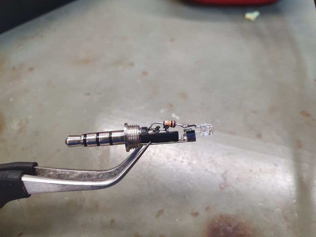
Then use a simple Android software, called Oscilloscope

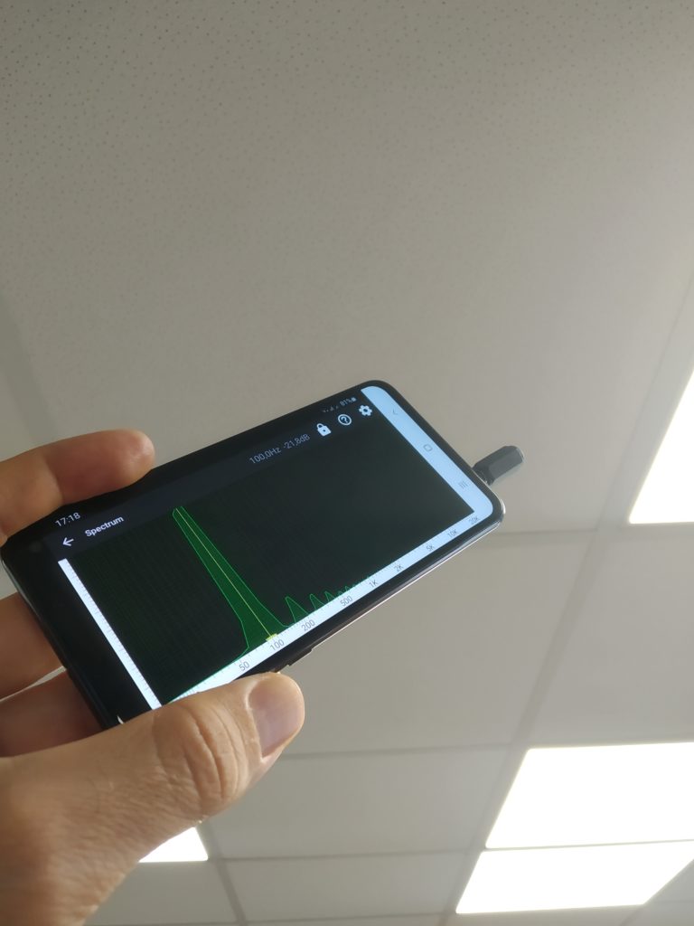
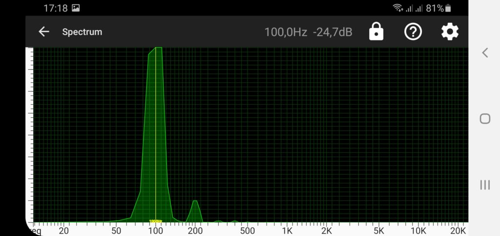
The result is then very straightforward, especially in spectrum analyzer:
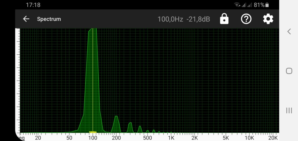
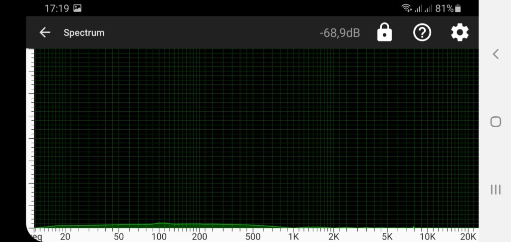
I now always have this small 3.5mm 4 ring photo-transistor adapter in my pocket when shopping light bulb/appliances in home improvement, so I can point it and discard the worst devices.
If someone comes up with a better idea, to measure more accurately amplitude and ideal the spectrum (would need a dedicated color sensor though), with an easy to use interface, that would be awesome.
]]>After fixing a TV with LED backlight, let’s dive in different performance of light fixture/light bulbs.
This effect is especially present in LED light fixtures where there is no inertia: incandescent or fluorescent light have a thermal or phosphor inertia and continue to glow a flick of second after the power is cut. But not the LED (even though there is some phosphor in them), this leads to have a close relation of the light intensity and the supply voltage.
Most of LED light bulb are supplied from main, the quality of the AC/DC converter takes a main role here. Because good rectification and filtering cost, manufacturer are cutting them, and you get this effect.
You can find two type of power supply on LED bulbs: simple rectification with LED string to match the AC rectified voltage. Or AC/DC converter with inductor and constant current control (this is what you want).
I wanted to “quantify” it, more that just a feeling, but didn’t want to drop hard cash (k€$ range) for dedicated equipment.
So I used one of the simplest and cheaper photo sensor on the market: a NPN phototransistor, (not a photoresistance as the bandwith is to small), in addition with a 10k resistor, connected to the GND (ring 2) and MIC (sleeve).
Then use a simple Android software, called Oscilloscope
The result is then very straightforward, especially in spectrum analyzer:
I now always have this small 3.5mm 4 ring photo-transistor adapter in my pocket when shopping light bulb/appliances in home improvement, so I can point it and discard the worst devices.
If someone comes up with a better idea, to measure more accurately amplitude and ideal the spectrum (would need a dedicated color sensor though), with an easy to use interface, that would be awesome.
]]>This model is a GRUNDIG 40VLE5324BG with LED backlight: not starting anymore (one could see the “Grunding” logo or “signal not present” when flashing a strong light on it).
After seeking the net for a solution, removing dozen of screws, accessing the 100cm long LCD panel made of ultra thin glass with COG and flex PCB on side, I finally had access to the culprit: No, it was not the capacitor, not the LED driver, not even a LED but a single connector: PCB to PCB connector, designed to decrease assembly time and cost. As these LED string are serial driven (140V @ 400mA), a single failure will render the whole system useless.
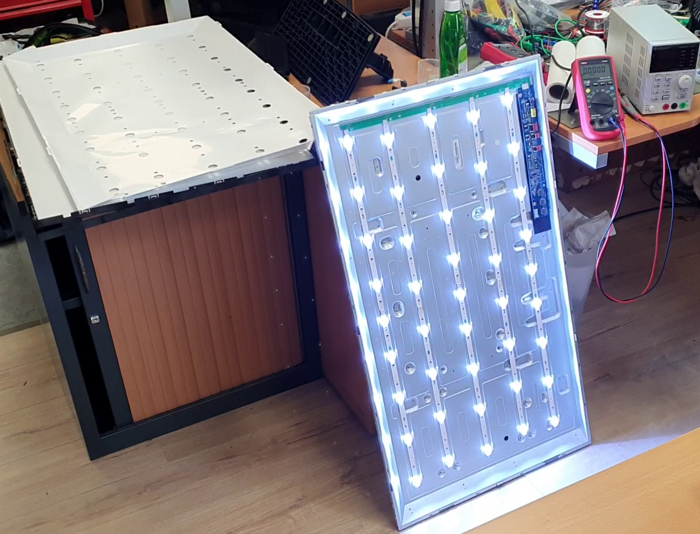
Just wiggling the connector would start/stop the backlight:
In this case, slight flex, oxidation or poor connector plating cause the problem, and as the LED as serial connected, the connector is oxidized from long arcing:
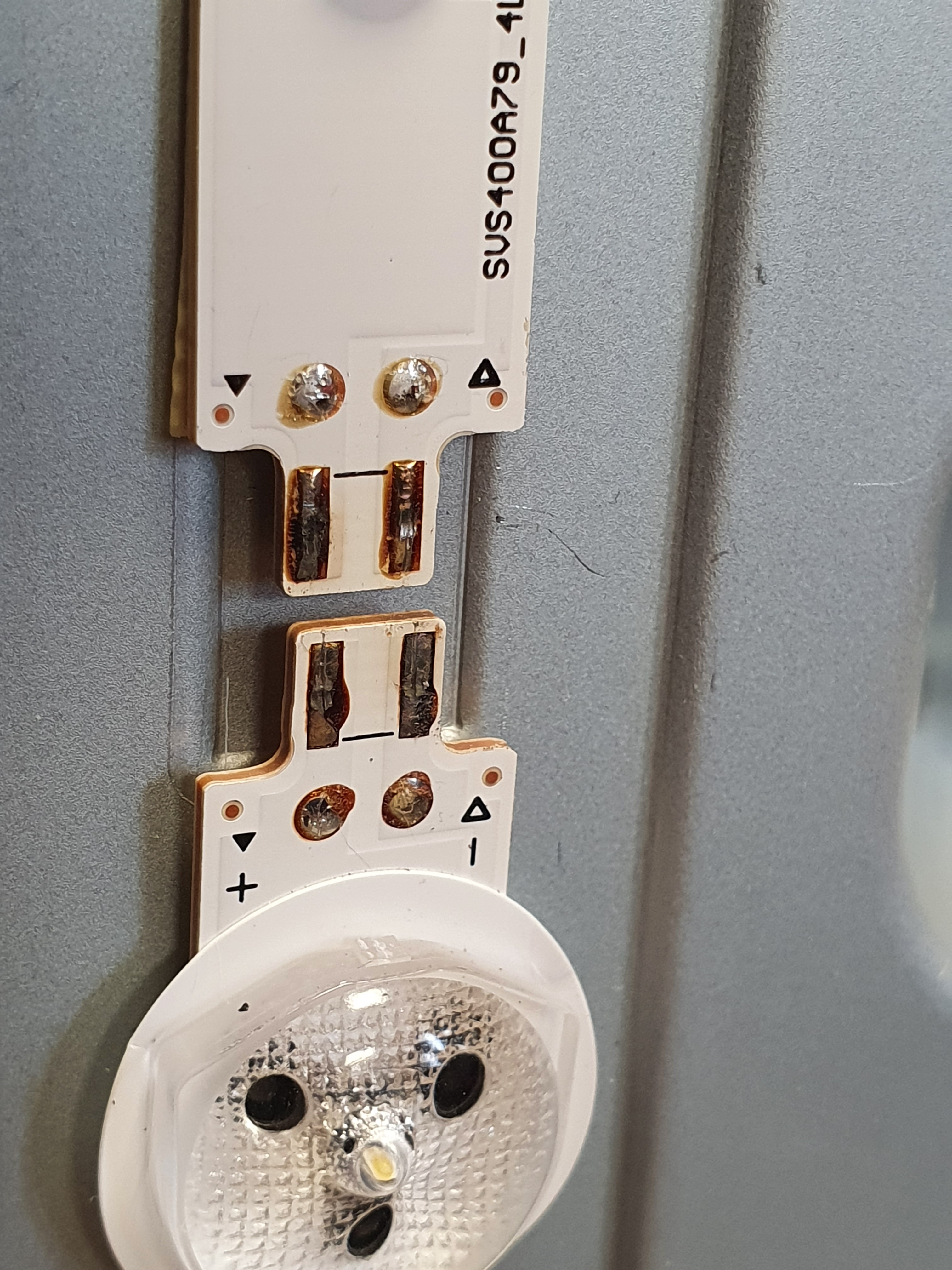
And the connector:
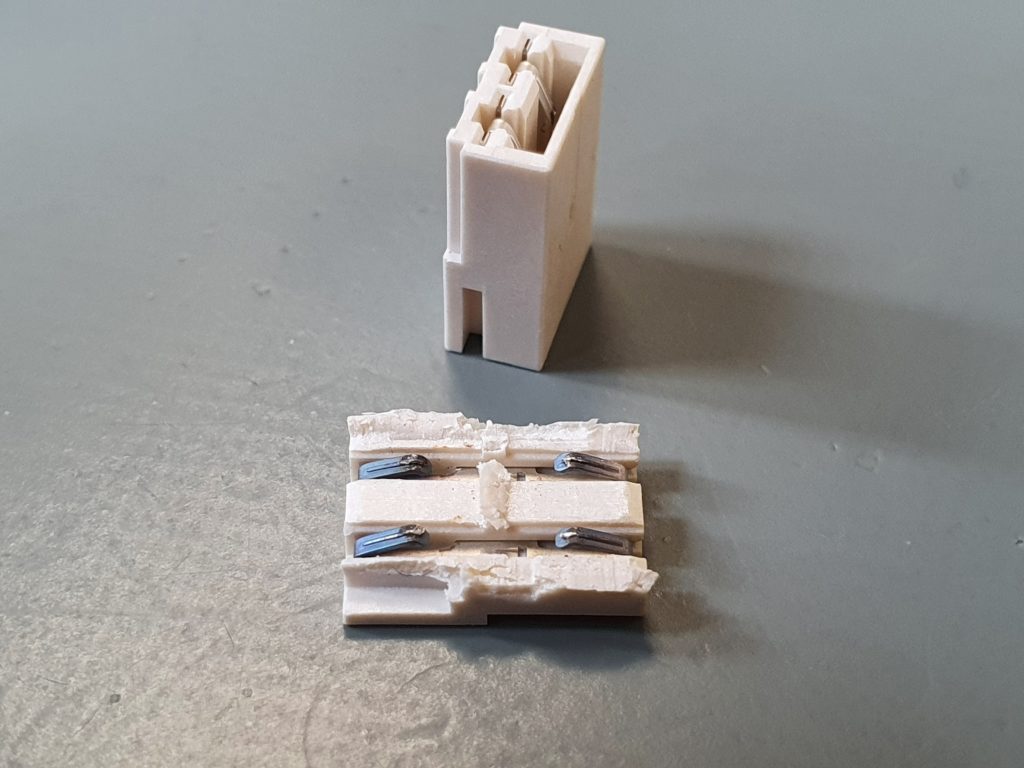
Let’s strap these connector with a piece of wire and fix this stuff!
Cheap 5ct clip will render a 500€/USD TV after few years! Hurray to planned obsolescence and global grow and economy!
]]>This model is a GRUNDIG 40VLE5324BG with LED backlight: not starting anymore (one could see the “Grunding” logo or “signal not present” when flashing a strong light on it).
After seeking the net for a solution, removing dozen of screws, accessing the 100cm long LCD panel made of ultra thin glass with COG and flex PCB on side, I finally had access to the culprit: No, it was not the capacitor, not the LED driver, not even a LED but a single connector: PCB to PCB connector, designed to decrease assembly time and cost. As these LED string are serial driven (140V @ 400mA), a single failure will render the whole system useless.
Just wiggling the connector would start/stop the backlight:
In this case, slight flex, oxidation or poor connector plating cause the problem, and as the LED as serial connected, the connector is oxidized from long arcing:
And the connector:
Let’s strap these connector with a piece of wire and fix this stuff!
Cheap 5ct clip will render a 500€/USD TV after few years! Hurray to planned obsolescence and global grow and economy!
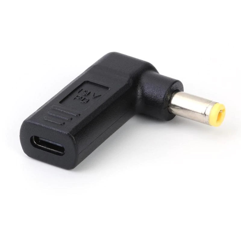
]]>While 12V DC jack DC5525 are everywhere, 24V are less but needed if you want more heat to solder larger components or grounds. (better than the TS-80 with the weak 18W anyway)
Supplying from USB-C source with PD 19V 60W takes full advantage of this iron solder.
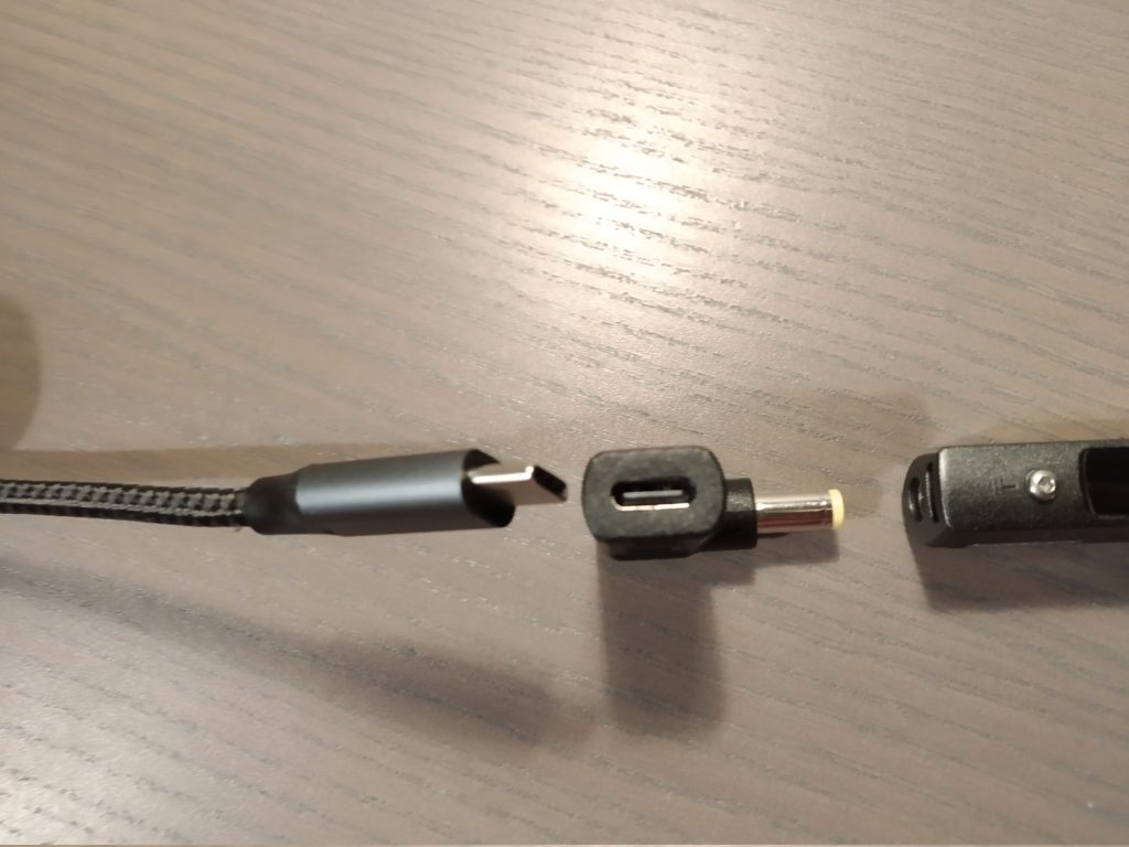
This hack has been made but not robust enough nor slick to my taste.
This 3 bucks USB-C to DC5.5mm @19V does the job.
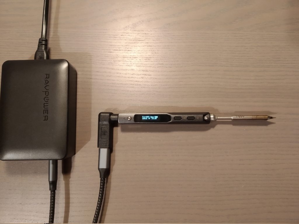
Here a RAVPower 60W PD is used
Perfect for my mobile bench with the classic DPS3005 power supply.
]]>While 12V DC jack DC5525 are everywhere, 24V are less but needed if you want more heat to solder larger components or grounds. (better than the TS-80 with the weak 18W anyway)
Supplying from USB-C source with PD 19V 60W takes full advantage of this iron solder.
This hack has been made but not robust enough nor slick to my taste.
This 3 bucks USB-C to DC5.5mm @19V does the job.
Here a RAVPower 60W PD is used
Perfect for my mobile bench with the classic DPS3005 power supply.
]]>
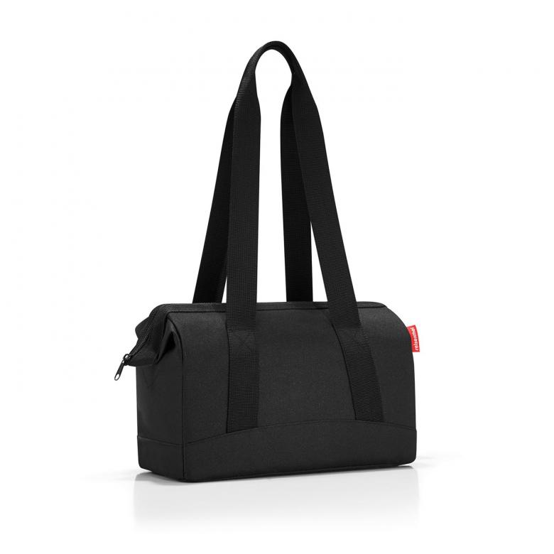
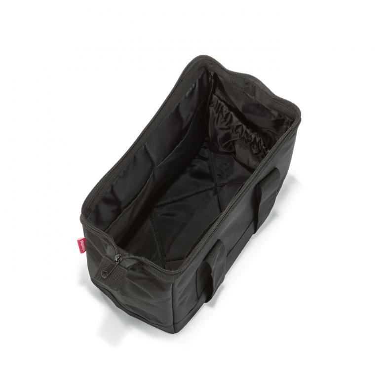
- Size (W x H x D): 32 x 24,5 x 16 cm
- Volume: 8 l
- Modeled after the traditional doctor’s bag: the contemporary interpretation of mobility!
- Lightly padded lateral walls and bottom
- Opening includes zip fastening and integrated metal bracket
- 6 inside pockets for practical storage
- 2 long carrying straps
- Material: premium-quality polyester, water-repellent
- Item no.: MR7003 EAN: 4012013546136

Well defined product functionality implemented with mature and state of the art industrial process can yield very nice products.
But in some cases, pushing sleekness over function don’t deserve the product well. This is especially the case for prosumer product: professional consumer want sturdy, rugged product, surviving the field.
Even a sales person on a show with a tablet for demo want certain level of toughness: the tablet can be drop by the visitor, will be abused during storage and transport, etc..
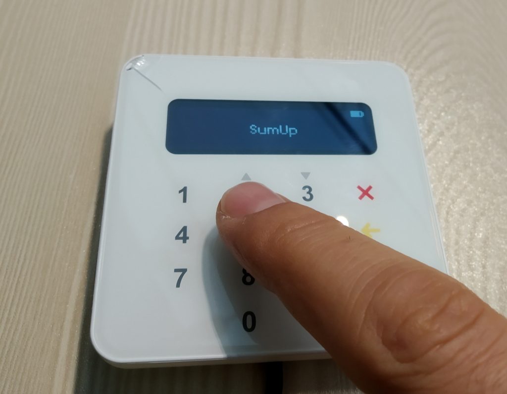
Today I want to talk about SumUp Air: a small payment terminal, synced with your smartphone to accept payment over 3G/4G or Wifi.
The idea is great: use your smartphone to do the accounting/sales stuff, while having a dedicated card reader with pin input Bluetooth synced to hand to the customer.
But the implementation is very, very poor.
After few years of use, I found out the following issues:
- the device is BLE: it’s always on, advertising every 10sec: this sucks as if you have it in your car with your stock, it is a plain beacon and screaming to be broken in
- the device cannot be switch off: yes, there is no way to switch it off. Contacting the support service, they told me you cannot even remove the battery as the signature/encryption key are in volatile memory (this is interesting as the battery must definitely be a li-po and can be over-discharged at some point)
- the keyboard interface is tactile (capacitive sensors), customer have trouble typing the pin in as there is no feedback of the switch press: why using a tactile technology for this!
- the front face is glass: just drop it and it will shatter: this is a field tool, the device WILL fall down, especially while handling it to customers, outdoors, etc..
- Bluetooth wake up and pairing is just a pain: while it’s supposed to wake up when you start the transaction on your smartphone, most of the time it doesn’t: you can to re-enable discovery/pairing on the front of you customer
- Location must be enabled on your smartphone: while this is interesting for transaction history, this is also a bad idea: it just drains the battery from your smartphone super fast.

]]>
Well defined product functionality implemented with mature and state of the art industrial process can yield very nice products.
But in some cases, pushing sleekness over function don’t deserve the product well. This is especially the case for prosumer product: professional consumer want sturdy, rugged product, surviving the field.
Even a sales person on a show with a tablet for demo want certain level of toughness: the tablet can be drop by the visitor, will be abused during storage and transport, etc..
Today I want to talk about SumUp Air: a small payment terminal, synced with your smartphone to accept payment over 3G/4G or Wifi.
The idea is great: use your smartphone to do the accounting/sales stuff, while having a dedicated card reader with pin input Bluetooth synced to hand to the customer.
But the implementation is very, very poor.
After few years of use, I found out the following issues:
- the device is BLE: it’s always on, advertising every 10sec: this sucks as if you have it in your car with your stock, it is a plain beacon and screaming to be broken in
- the device cannot be switch off: yes, there is no way to switch it off. Contacting the support service, they told me you cannot even remove the battery as the signature/encryption key are in volatile memory (this is interesting as the battery must definitely be a li-po and can be over-discharged at some point)
- the keyboard interface is tactile (capacitive sensors), customer have trouble typing the pin in as there is no feedback of the switch press: why using a tactile technology for this!
- the front face is glass: just drop it and it will shatter: this is a field tool, the device WILL fall down, especially while handling it to customers, outdoors, etc..
- Bluetooth wake up and pairing is just a pain: while it’s supposed to wake up when you start the transaction on your smartphone, most of the time it doesn’t: you can to re-enable discovery/pairing on the front of you customer
- Location must be enabled on your smartphone: while this is interesting for transaction history, this is also a bad idea: it just drains the battery from your smartphone super fast.
]]>
But most of them due to the card tray design, can either accept:
- two SIM but no micro-SD
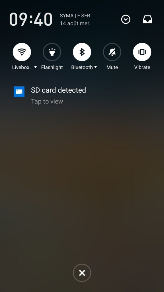
- one SIM and a micro-SD card
This is definitely a bugger since mid-range Android smartphones are pretty stingy with storage memory (from 16Gb to 32Gb), while micro SD are pretty cheap an wayyyyy larger (128Gb to 512Gb)
Here is the quick hack to insert both dual sim, and a micro SD.
Tools needed
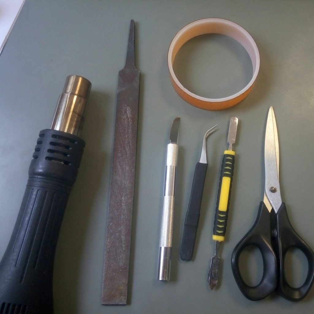
Tools needed, but a lighter and utility knife would do 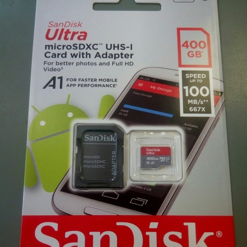
Wow, 400Gb
Peel the back of the nano-SIM plastic, with a hot air gun, as it’s soften the back glue, heat gently and evenly the back, to not fry the sim. (you may want to try first with a discarded SIM card, sitting in your junk-box)
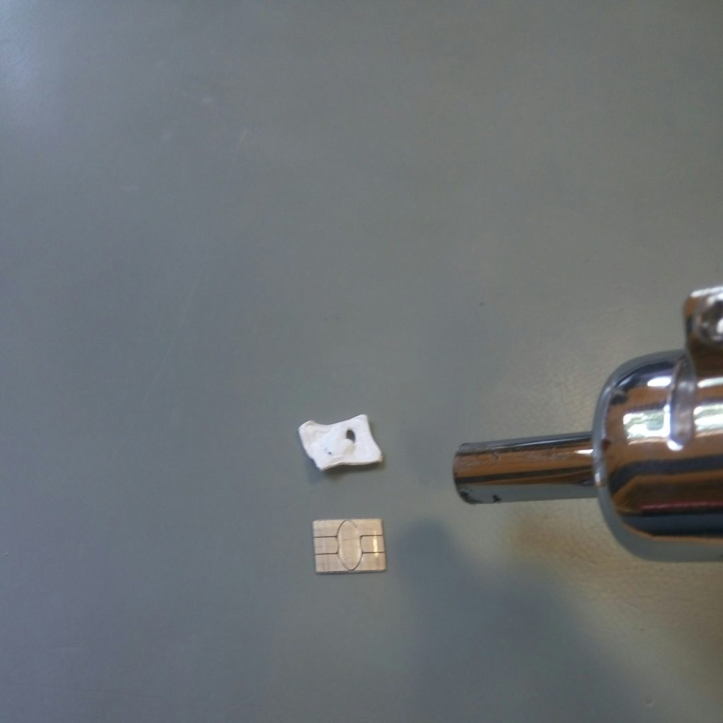
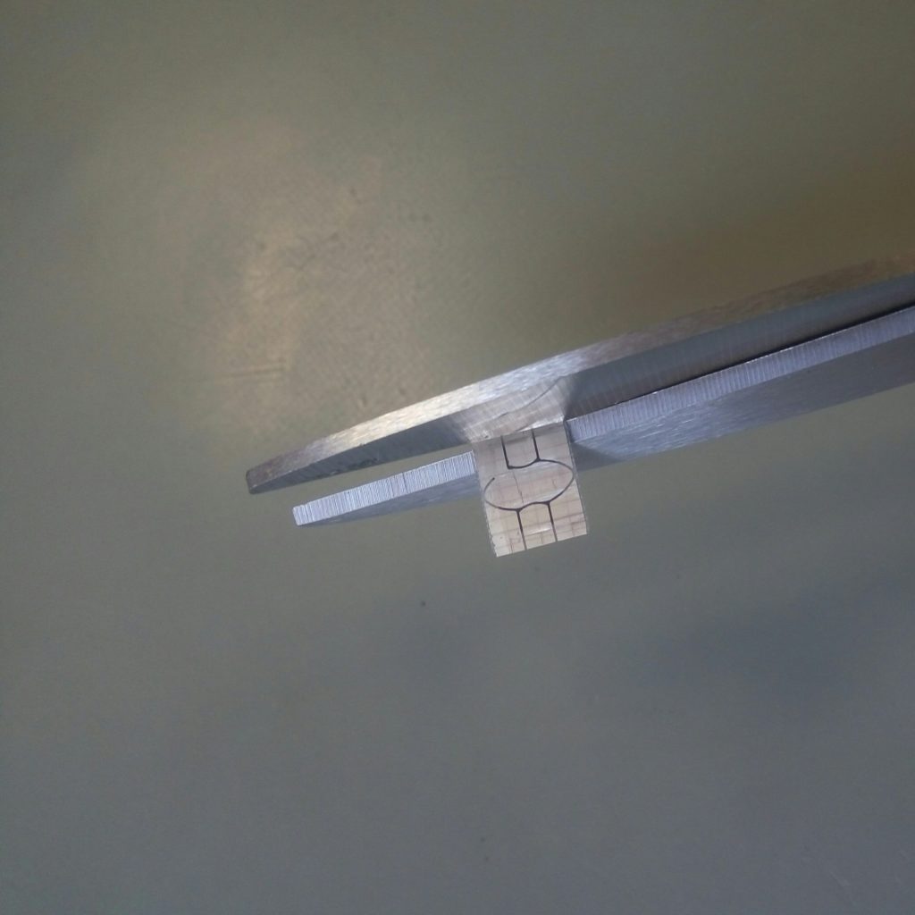
Clip about 1mm the sides of the FR4 epoxy SIM card
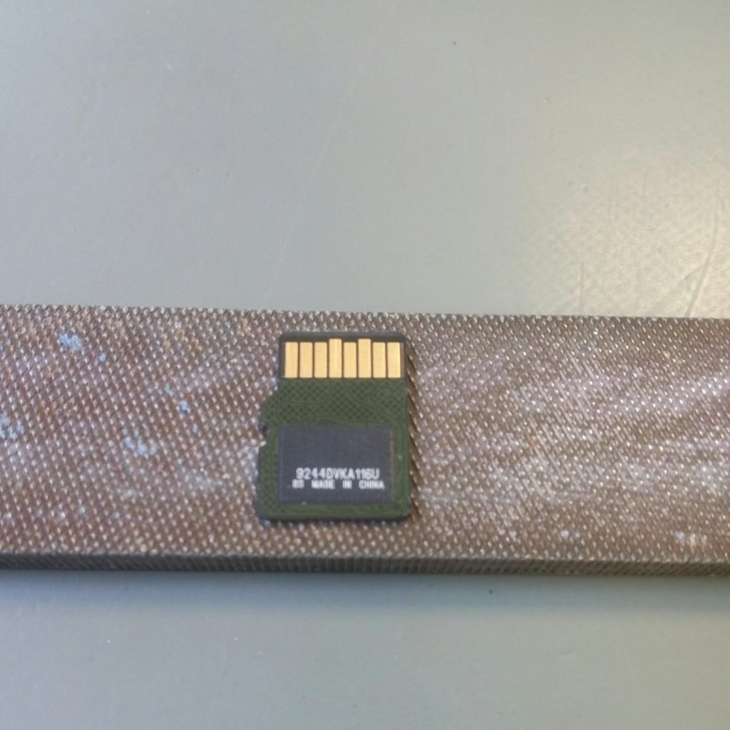
File the edge on the micro SD card, so it’s thinner, and don’t have this edge protruding anymore and shaves few microns of the card.
It’s interesting the flipchip design, reflown or wire bonded on a thin PCB with the finger contacts, then overmolded with the final plastic case. 400Gb are store in this die, that’s awesome, I guess, the controller must be integrated too, not separated as in Bunnie’s entry: https://www.bunniestudios.com/blog/?page_id=1022
I don’t know if one can reflow this design as experimented here: http://www.dotmana.com/weblog/2015/08/microsd-card-reflow-quick-and-dirty-pcb-with-kicad/
micro SD card on file 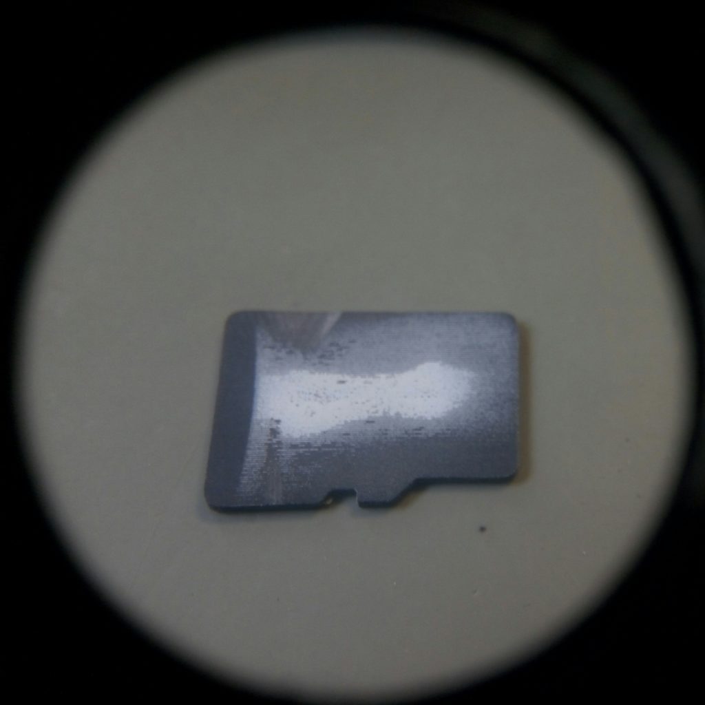
Filed top micro SD, luckily, there is no SMD caps hidden in this notch
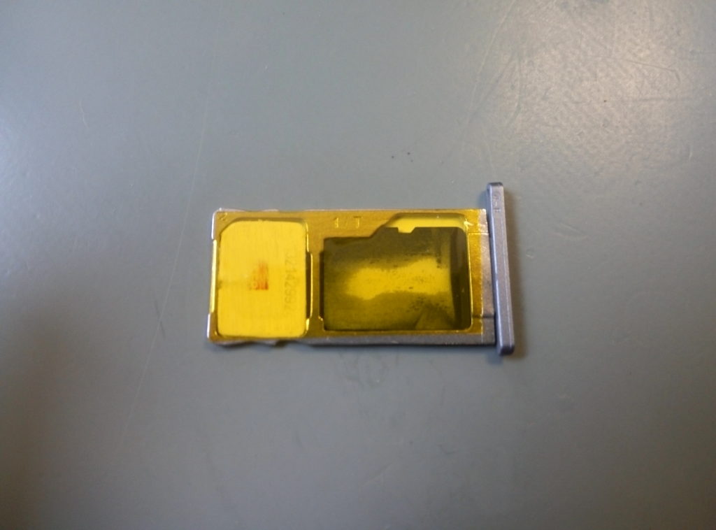
Tape one side of the smartphone card tray, with the first sim card and the micro-SD
Tape the other side with the shrinked second SIM
(take extra care where the chip should align, here I made scratches with the scalpel with the unmodified nano sim where it should go)
Here I used Kapton tape, but I guess any office tape would do
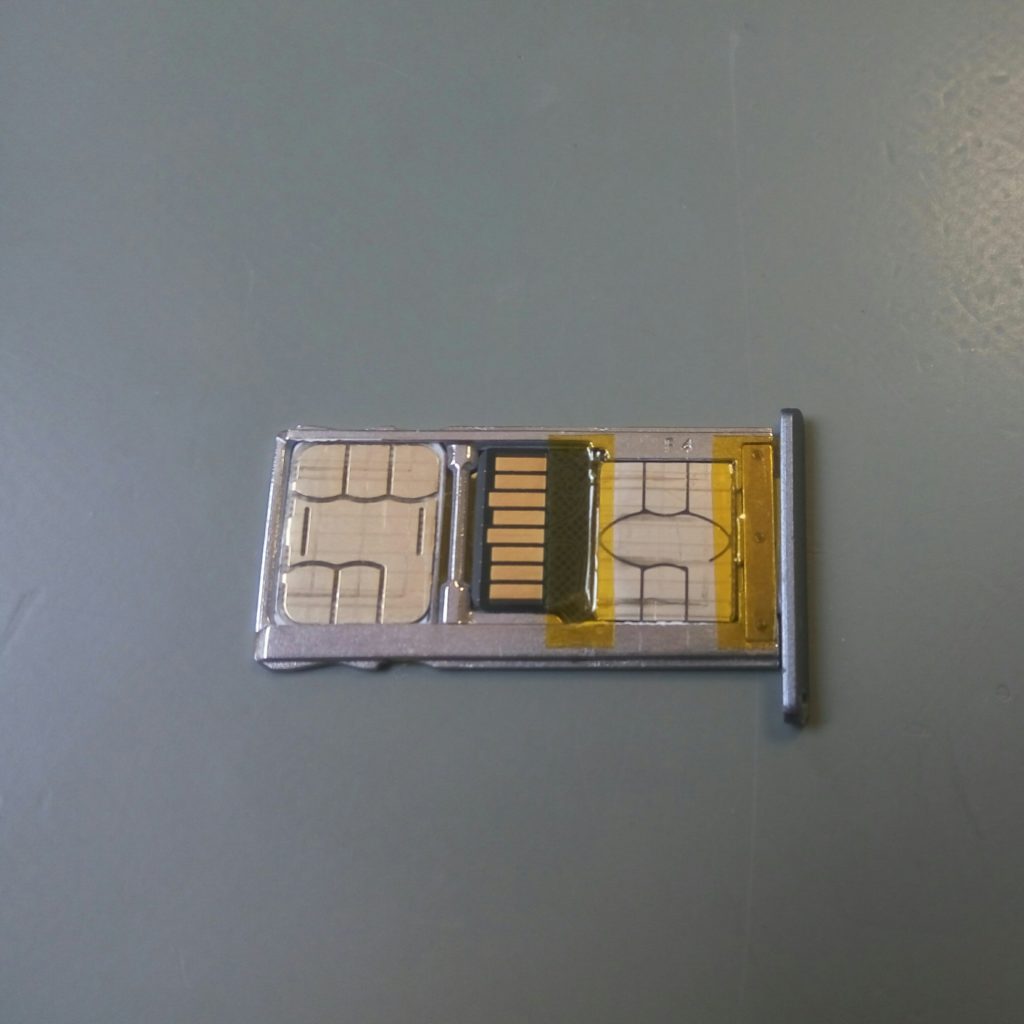
That’s it! Dual sim and lot of storage! 400Gb, gosh!
But most of them due to the card tray design, can either accept:
- two SIM but no micro-SD
- one SIM and a micro-SD card
This is definitely a bugger since mid-range Android smartphones are pretty stingy with storage memory (from 16Gb to 32Gb), while micro SD are pretty cheap an wayyyyy larger (128Gb to 512Gb)
Here is the quick hack to insert both dual sim, and a micro SD.
Tools needed
Tools needed, but a lighter and utility knife would do Wow, 400Gb
Peel the back of the nano-SIM plastic, with a hot air gun, as it’s soften the back glue, heat gently and evenly the back, to not fry the sim. (you may want to try first with a discarded SIM card, sitting in your junk-box)
Clip about 1mm the sides of the FR4 epoxy SIM card
File the edge on the micro SD card, so it’s thinner, and don’t have this edge protruding anymore and shaves few microns of the card.
It’s interesting the flipchip design, reflown or wire bonded on a thin PCB with the finger contacts, then overmolded with the final plastic case. 400Gb are store in this die, that’s awesome, I guess, the controller must be integrated too, not separated as in Bunnie’s entry: https://www.bunniestudios.com/blog/?page_id=1022
I don’t know if one can reflow this design as experimented here: http://www.dotmana.com/weblog/2015/08/microsd-card-reflow-quick-and-dirty-pcb-with-kicad/
micro SD card on file Filed top micro SD, luckily, there is no SMD caps hidden in this notch
Tape one side of the smartphone card tray, with the first sim card and the micro-SD
Tape the other side with the shrinked second SIM
(take extra care where the chip should align, here I made scratches with the scalpel with the unmodified nano sim where it should go)
Here I used Kapton tape, but I guess any office tape would do
That’s it! Dual sim and lot of storage! 400Gb, gosh!
You want to build stuff to last? Go to the moon? That’s the only way to go.
Here is the online version from NASA:
https://workmanship.nasa.gov/lib/insp/2%20books/frameset.html
And my home built PDF version:
]]> NASA_workmanship_standard_pictorial_reference.pdf
You want to build stuff to last? Go to the moon? That’s the only way to go.
Here is the online version from NASA:
https://workmanship.nasa.gov/lib/insp/2%20books/frameset.html
And my home built PDF version:
]]>This is based on the famous DPS3005 (about 25€)

Let’s 3D print an enclosure, found on Thingiverse:
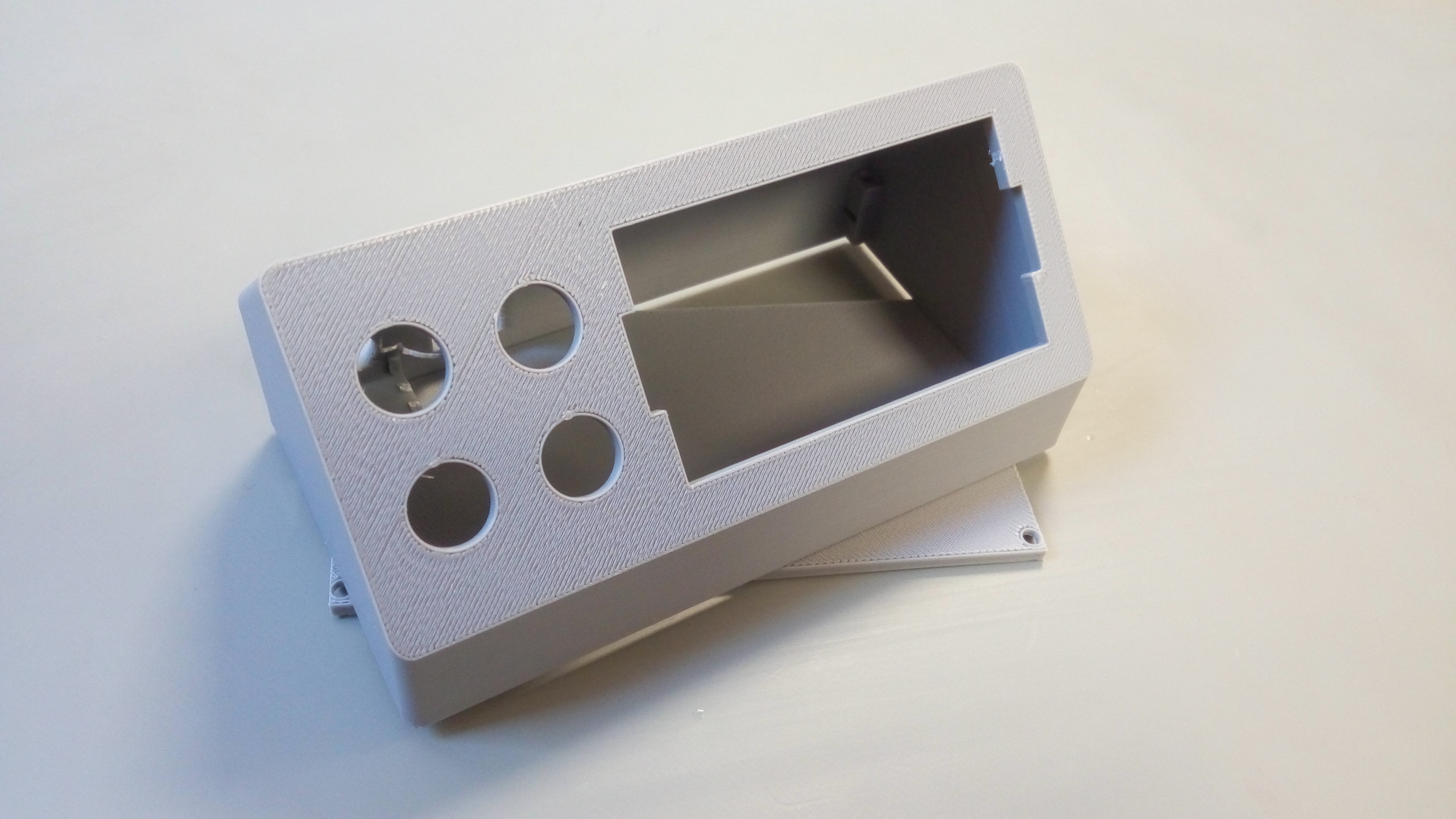
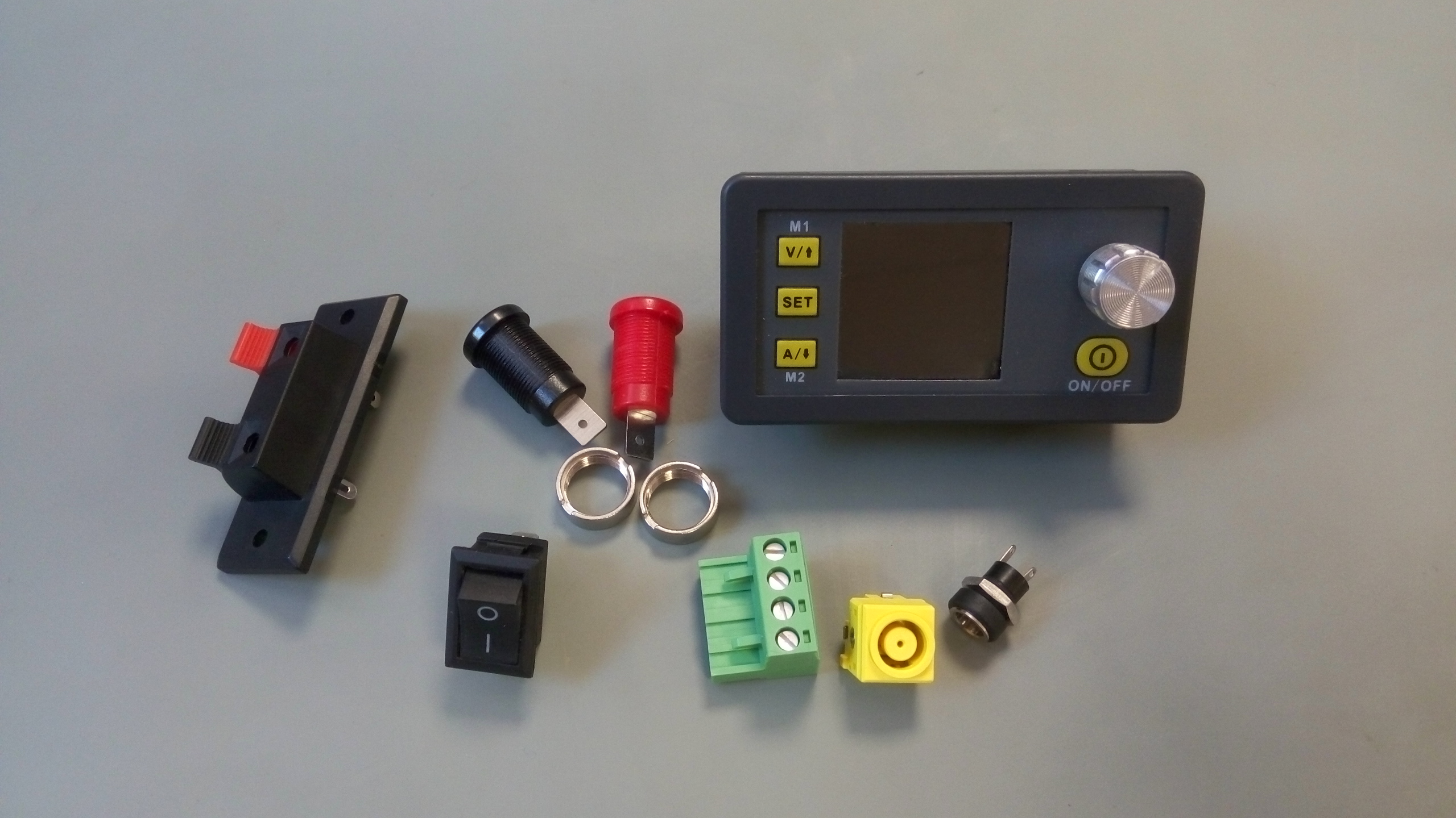
And grab all the jelly beans needed:
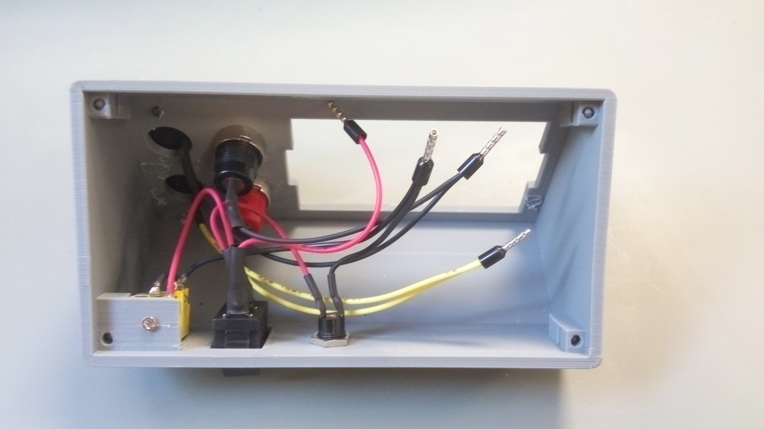
Wire/crimp/solder:
Does work quite well:
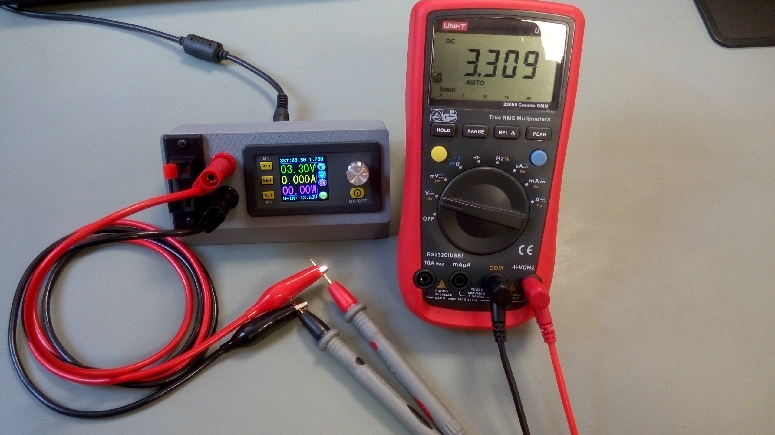
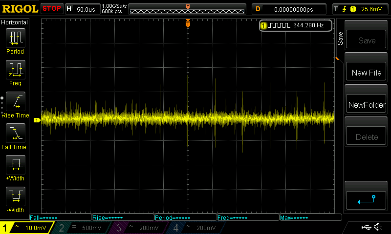
With not much noise (static 100mA load):
And as I’ve this fancy portable solder iron with a bunch of li-ion cell:
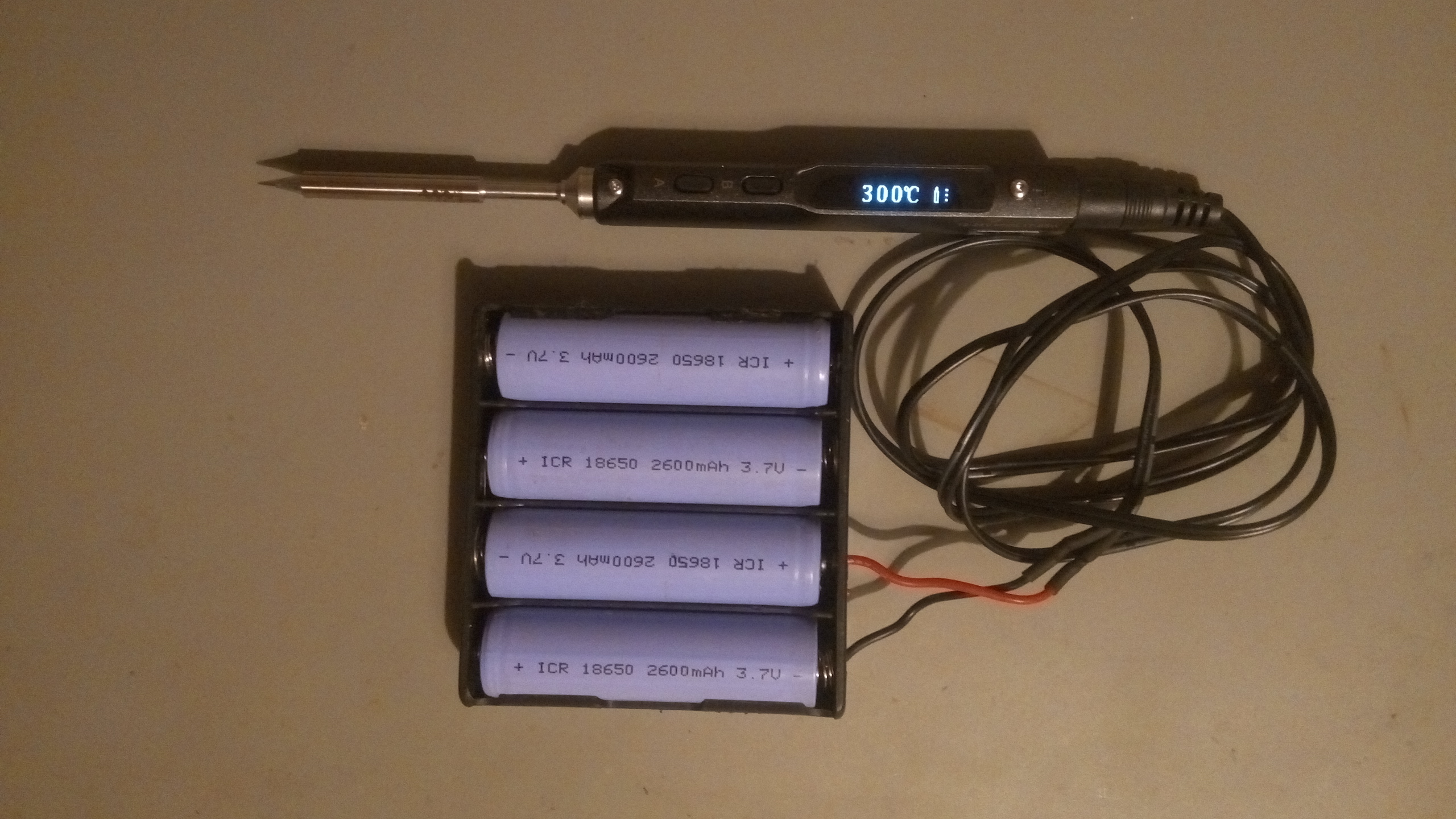
It works on the road!
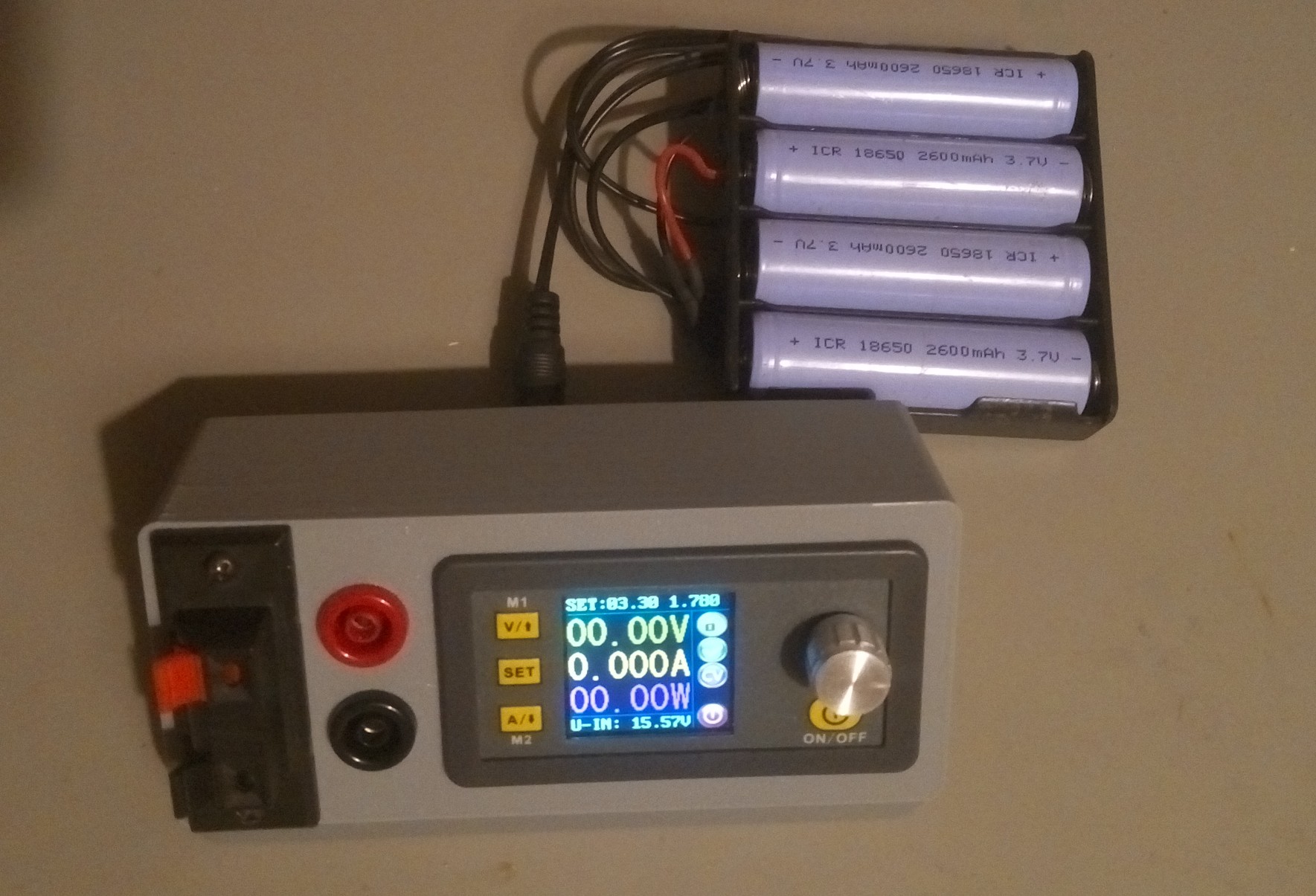
This is based on the famous DPS3005 (about 25€)
Let’s 3D print an enclosure, found on Thingiverse:
And grab all the jelly beans needed:
Wire/crimp/solder:
Does work quite well:
With not much noise (static 100mA load):
And as I’ve this fancy portable solder iron with a bunch of li-ion cell:
It works on the road!
We love to listen to FIP, as it’s a public radio, without commercials and not so much speaking.
Unfortunately, this radio is FM brodcasted in only few city in France, and here in Grenoble, the only way to get is internet.
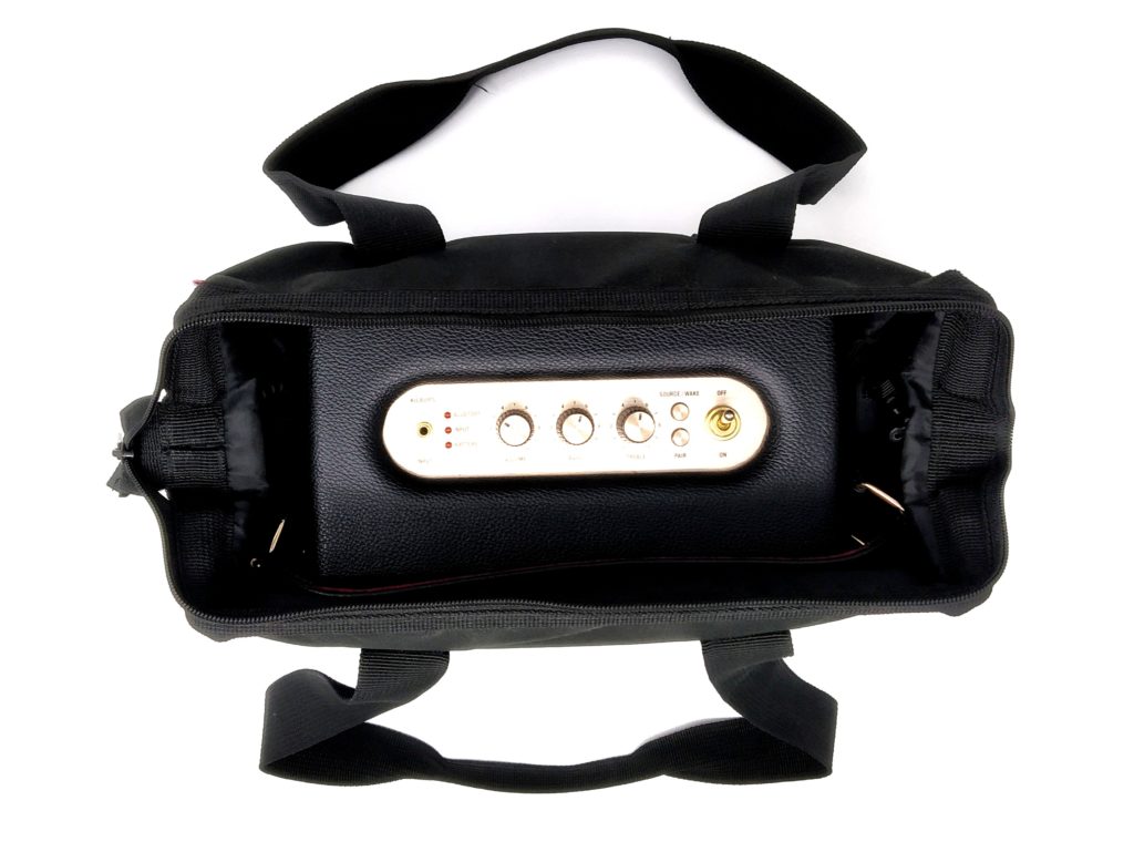
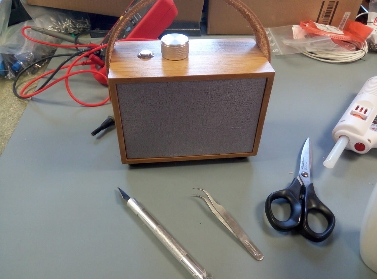
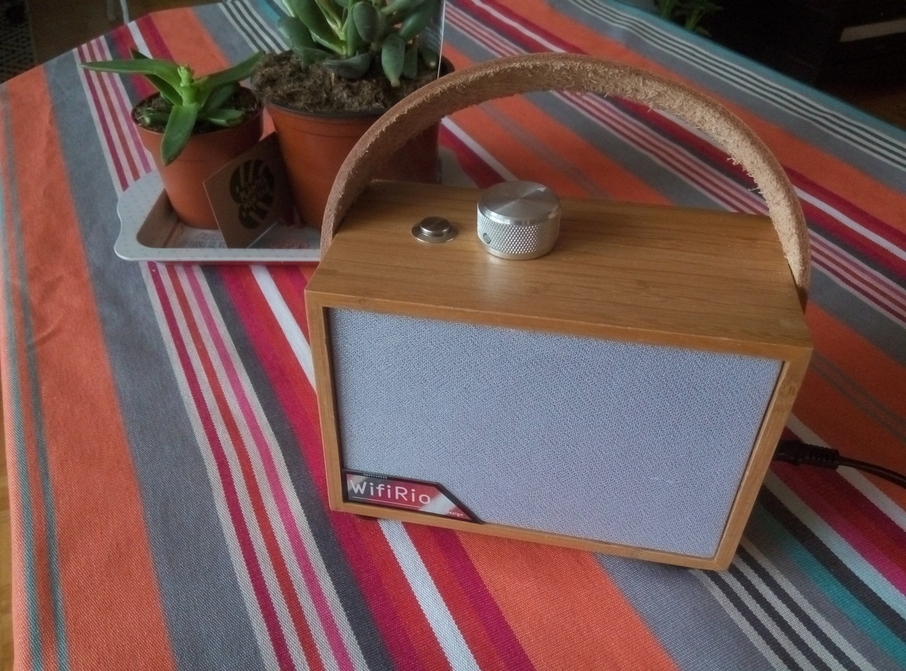
So we built this small kitchen radio, music playing in 14 seconds, and quite pleasantly aesthetic, in the same line as my previous nixie clock.
The large solid aluminium knob with amplifier pot ON/OFF produces a comforting click to power ON/OFF the device or adjust the volume.
The shiny stainless steel button is for future upgrade to allow changing from few radio as currently only one is available.
Hardware part
Here are almost all the items needed for this DIY hack:
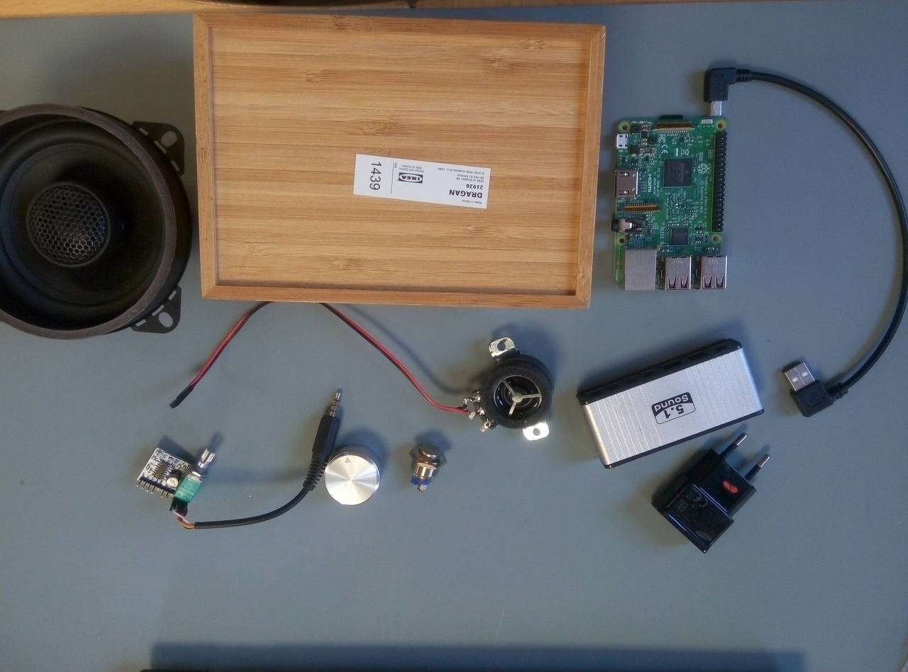
- Ikea box (4€)
- 4″ coax speaker (scrap)
- 1″ tweeter (3€ on AE)
- Rpi 3b (40€ on Farnell)
- USB sound card (5€ on AE)
- Stereo 5V amplifier (1€ on AE)
- aluminium knob (5€ on AE)
- stainless steel push button (1€ on AE)
- C5 pannel connector for main supply (0.1€ on AE)
- USB wall wart (scrap)
- piece of 5mm plywood (scrap)
- speaker fabric for front pannel (4€ on AE)
- 30cm of leather belt (scrap)
- washed nuts (1€ on AE)
A total of about 60€
Step by step assembly
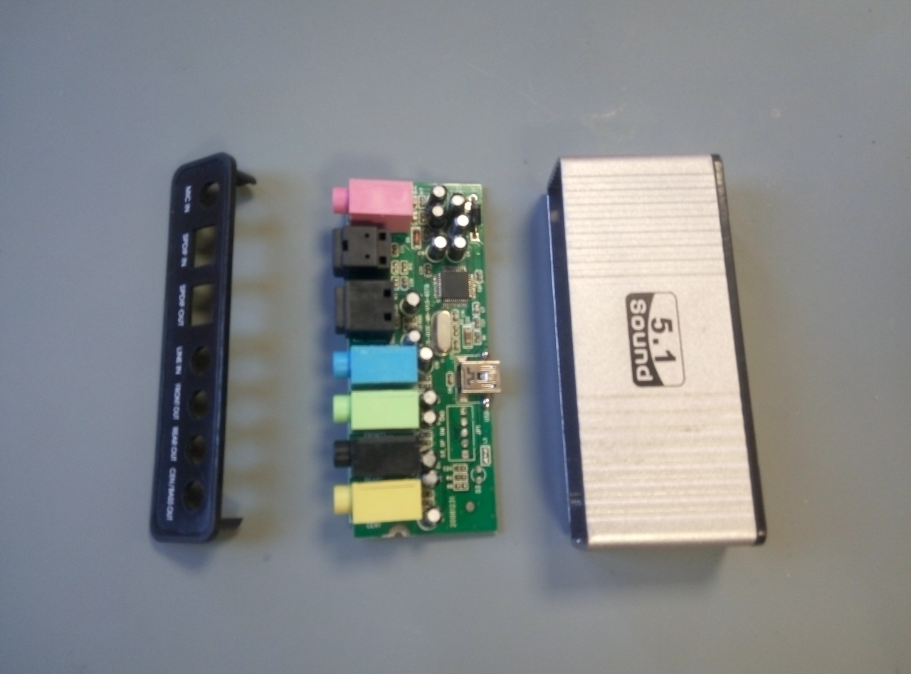 Let’s remove the USB sound card along with the extra not needed capacitors and jack connector (desoldering station is realy a must here)
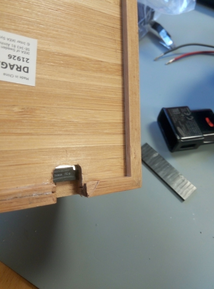
Make a slot for the micro SD card on the back: remember, the Wifi credential are stored here.
A XY table on a drill press was usefull, I didnt imagine bamboo being so hard to mill.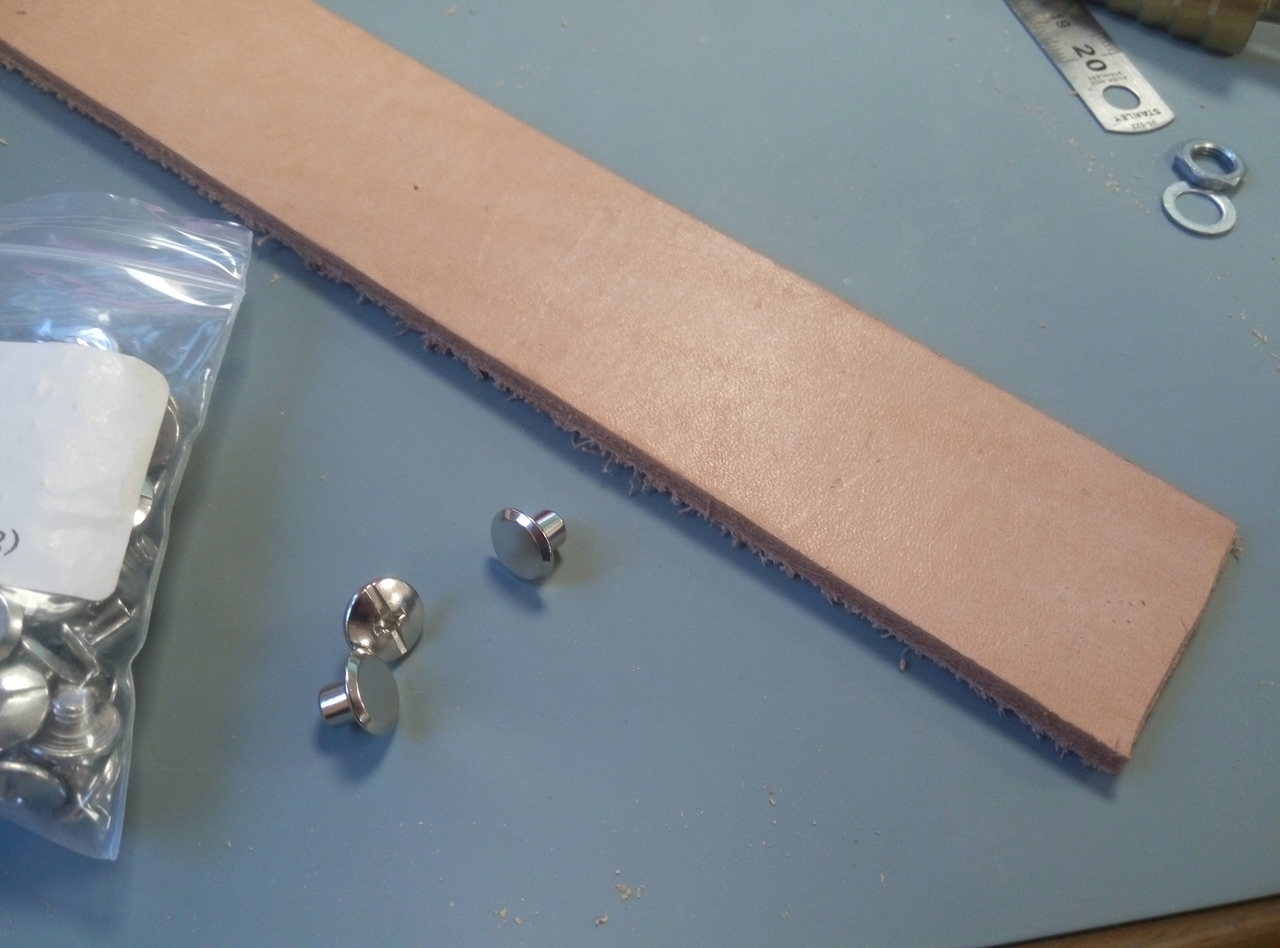
Piece of leather bought in Texas, this is what’s left from my buckle-less belt I made few years ago, it could be an entry someday.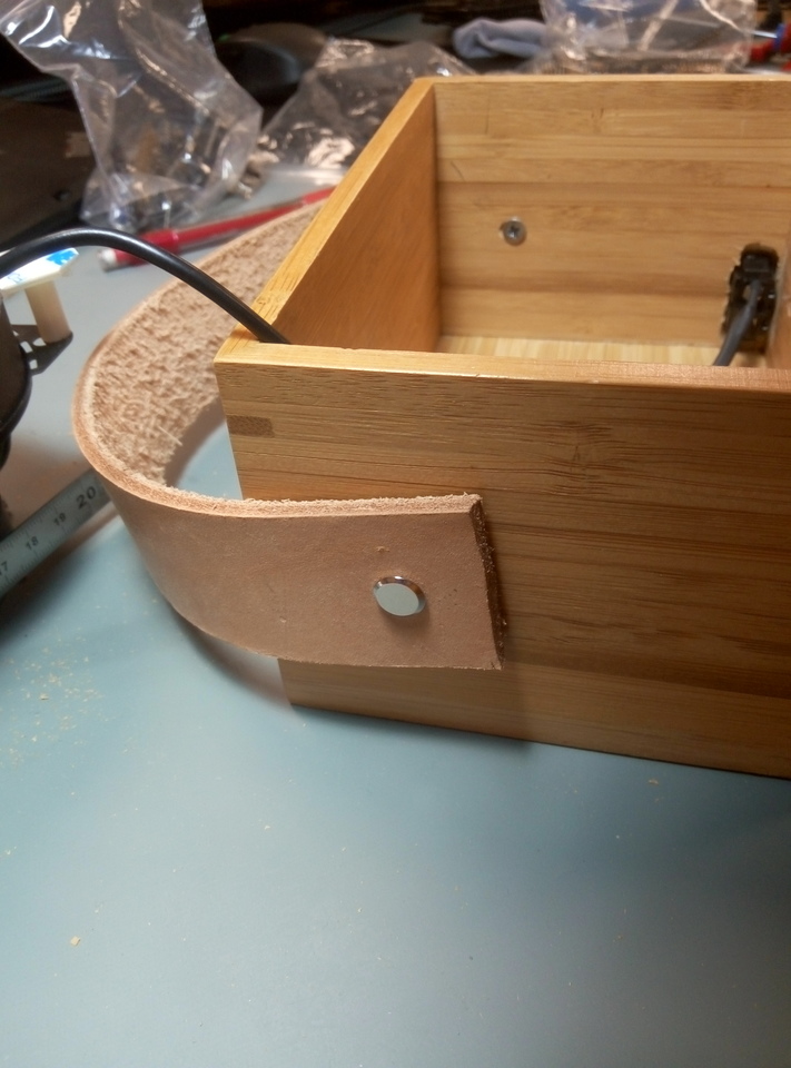
With the washer nuts, it look nice.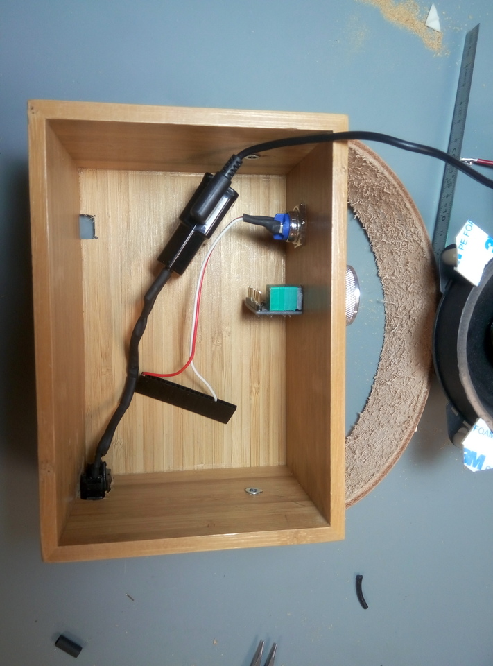
The C8 pannel connector, wired to the wall wart.
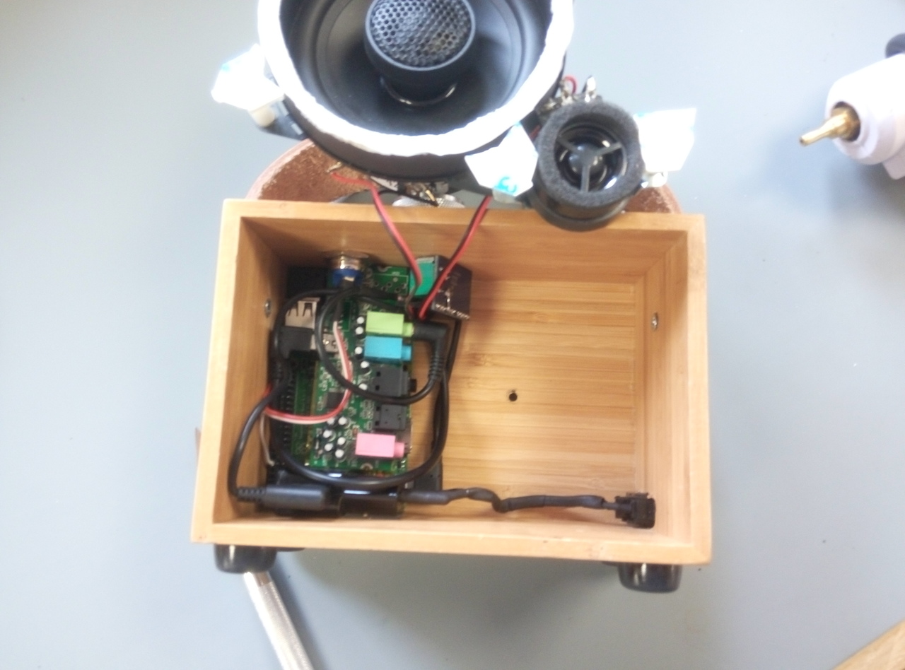
Everything fitted in the box, held in place with double side tape (the brand Multicomp from Farnell is nice).
Adhesive rubber feet add an extra touch.
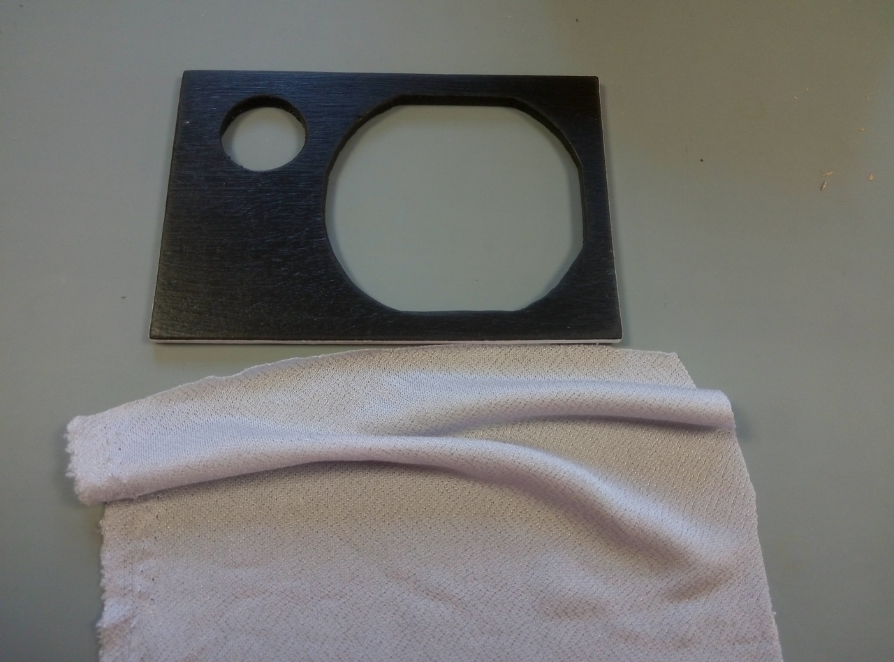
Piece of plywood for the front panel, black mate painted, with the speaker cloth.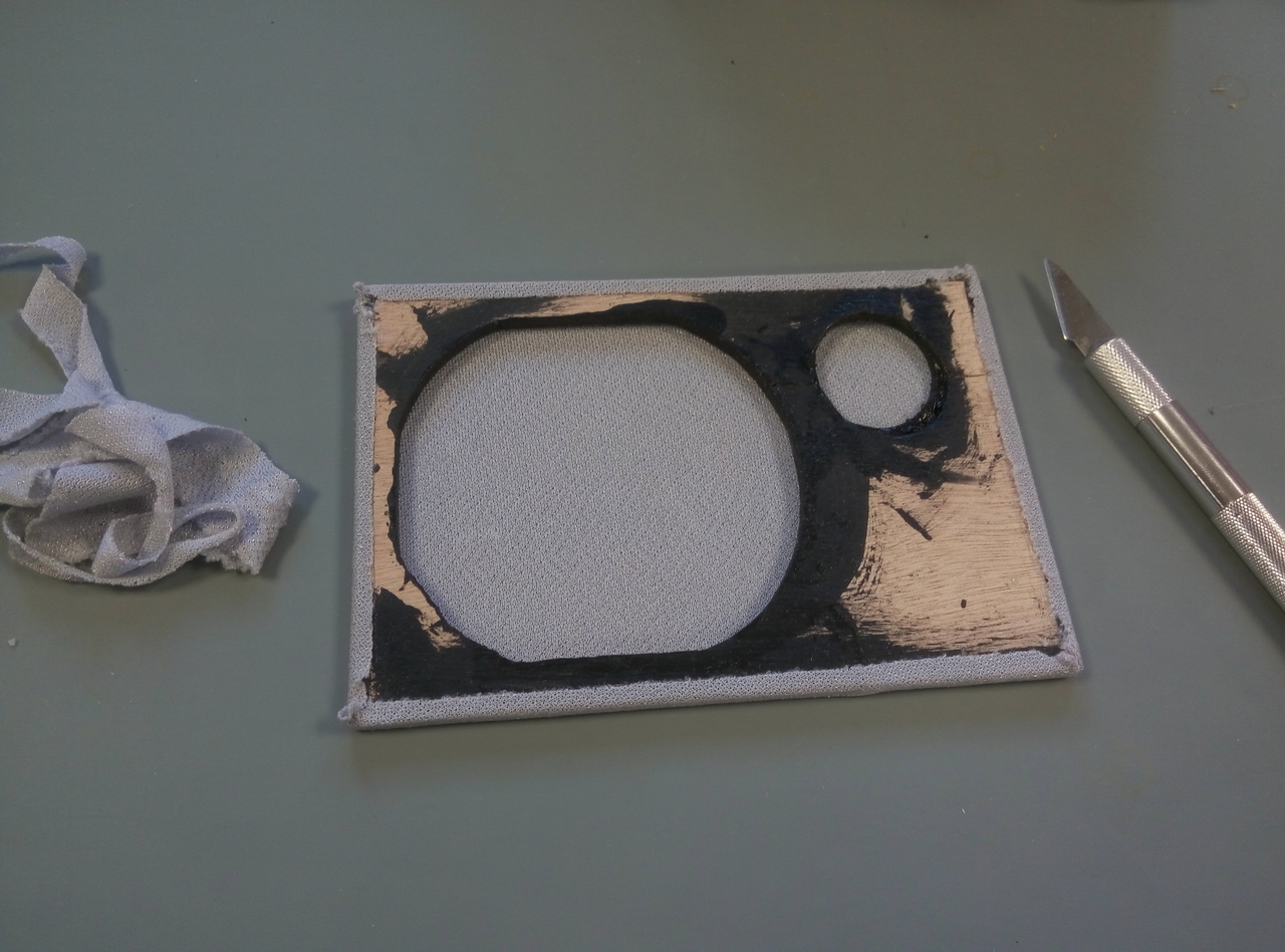
Held in place with thin double side tape.
Finish
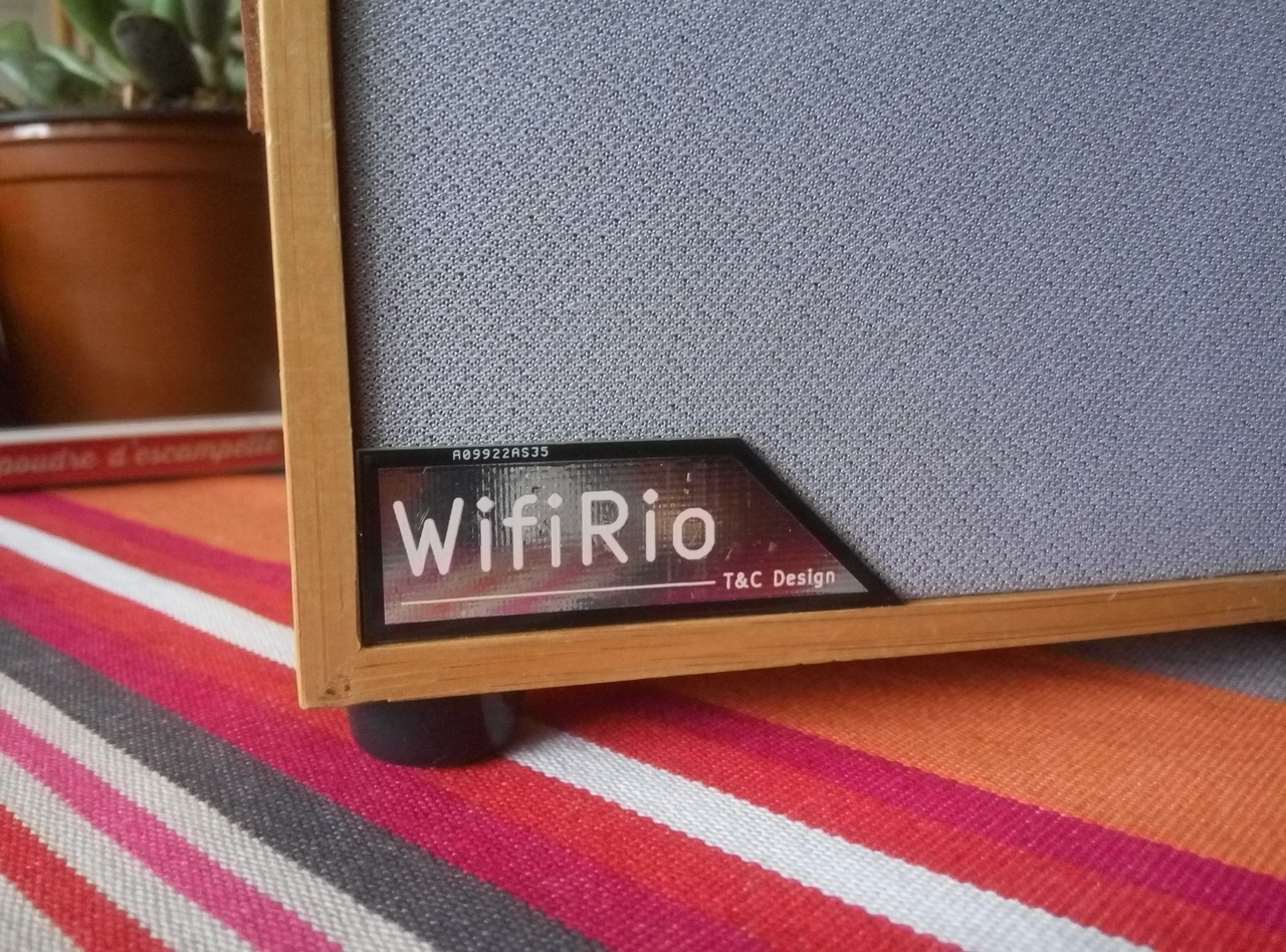
Let’s add a small tag to give some identity to this yet unbranded product. A nice friendly name, with our initials to personalize it even more.
Warm up kicad and start just a PCB without schematics, with a beveled edge to add a touch of design: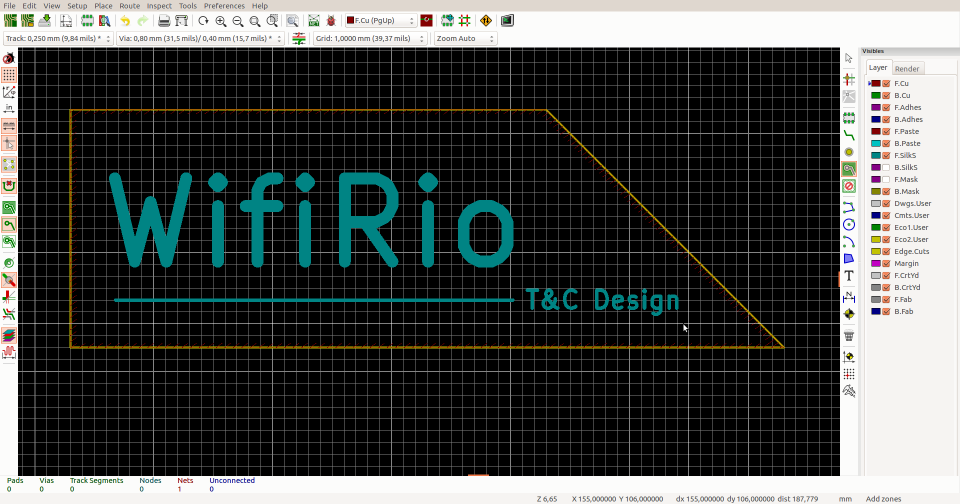
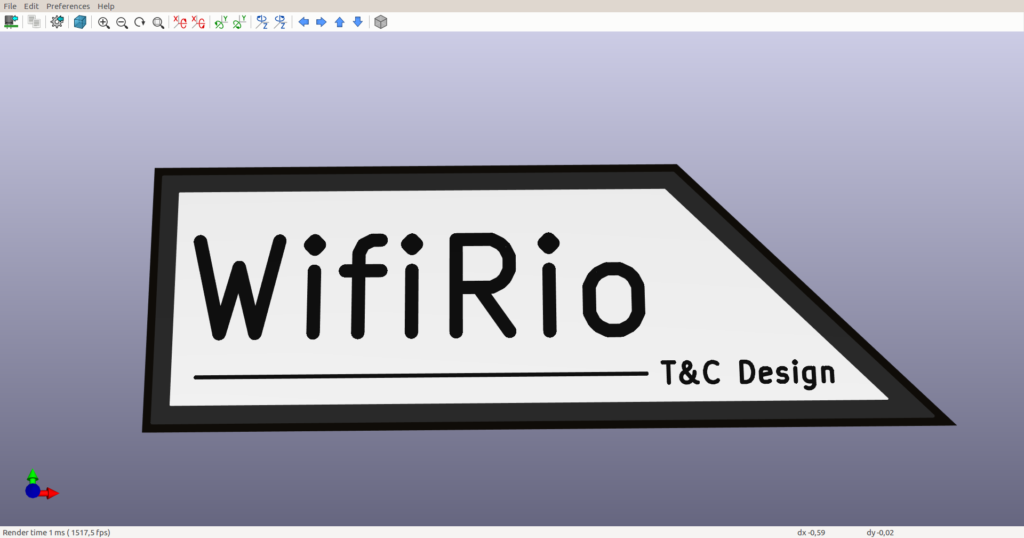
The result is very good, with this mirror finish!
Once glued on the product, it does raise the bar. (a pitty the manufacturing reference is on the front, next time I’ll do my artwork on the back, just to make sure it’s not on the front)
A quick video:
Software part
Download RPI image
Download a RPI image, in this case, I choose : pipaOS A lighweight, fast, Raspbian based distro for the Raspberry PI
Once the image unziped, copy to a fresh high performance micro SD card
sudo dd bs=4M if=./pipaos-tamarillo-4.7.img of=/dev/mmcblk0
in order to boost performances, I use a Samsung EVO+ for high performance for a very fast boot
ssh sysop@192.168.1.84 (password posys)
Connect to WIFI network
Rpi 3 rev B and Zero W have integrated wifi
Edit WIFI credentials
The file /etc/network/interfaces should NOT be modified, as it’s overwritten at start.
Edit the file
sudo nano /boot/network.ini
To add your credential:
#
 # interfaces - setup your networking devices here
 #

auto lo
 iface lo inet loopback

allow-hotplug eth0
 iface eth0 inet dhcp

allow-hotplug usb0
 iface usb0 inet dhcp

# pipaOS Will automatically try to connect
 # to wireless ESSID "pipaos" passphrase "pipa123pass"
 allow-hotplug wlan0
 iface wlan0 inet dhcp
 wpa-ssid YOUR_SSSID
 wpa-psk YOUR_WIFI_KEY
High quality sound
Rasberry Pi have 3.5mm stereo jack output but the quality is pure crap, wondering why they even bother populate a jack.
So lets connect a cheap UBS sound card and check what appends
dmesg
sould display something like
[ 106.865142] usb 1-1.2: new full-speed USB device number 5 using dwc_otg
 [ 107.006372] usb 1-1.2: New USB device found, idVendor=0d8c, idProduct=0102
 [ 107.006387] usb 1-1.2: New USB device strings: Mfr=0, Product=2, SerialNumber=0
 [ 107.006395] usb 1-1.2: Product: USB Sound Device

[ 107.042816] input: USB Sound Device as /devices/platform/soc/3f980000.usb/usb1/1-1/1-1.2/1-1.2:1.3/0003:0D8C:0102.0002/input/input1
 [ 107.105630] hid-generic 0003:0D8C:0102.0002: input,hidraw0: USB HID v1.00 Device [USB Sound Device ] on usb-3f980000.usb-1.2/input3
and
lsusb
will output:
 Bus 002 Device 009: ID 0d8c:0102 C-Media Electronics, Inc. CM106 Like Sound Device
 Bus 002 Device 001: ID 1d6b:0002 Linux Foundation 2.0 root hub
 Bus 001 Device 001: ID 1d6b:0002 Linux Foundation 2.0 root hub
Create startup service : webradio
sudo apt-get install mplayer
mplayer `curl -w "%{url_effective}\n" -I -L -s -S http://direct.fipradio.fr/live/fip-midfi.mp3 -o /dev/null`
Webradio player script
create non returning script:
sudo nano /home/sysop/webradio.sh
while true
 do mplayer http://chai5she.cdn.dvmr.fr:80/fip-midfi.mp3
 sleep 1
 done
create init.d service: webradio
#!/bin/bash
 #webradio daemon
 # chkconfig: 345 20 80
 # description: mwebradioapp daemon
 # processname:webradio

DAEMON_PATH="/"

DAEMON=/home/sysop/webradio.sh
 DAEMONOPTS=""

NAME=myapp
 DESC="My daemon description"
 PIDFILE=/var/run/$NAME.pid
 SCRIPTNAME=/etc/init.d/$NAME

case "$1" in
 start)
 printf "%-50s" "Starting $NAME..."
 cd $DAEMON_PATH
 PID=`$DAEMON $DAEMONOPTS > /dev/null 2>&1 & echo $!`
 #echo "Saving PID" $PID " to " $PIDFILE
 if [ -z $PID ]; then
 printf "%s\n" "Fail"
 else
 echo $PID > $PIDFILE
 printf "%s\n" "Ok"
 fi
 ;;
 status)
 printf "%-50s" "Checking $NAME..."
 if [ -f $PIDFILE ]; then
 PID=`cat $PIDFILE`
 if [ -z "`ps axf | grep ${PID} | grep -v grep`" ]; then
 printf "%s\n" "Process dead but pidfile exists"
 else
 echo "Running"
 fi
 else
 printf "%s\n" "Service not running"
 fi
Install startup service
update-rc.d webradio defaults
Start service manually
sudo service webradio start
Check startup time and performance
Startup time with RPI 3 B: Startup finished in 2.602s (kernel) + 4.386s (userspace) = 6.988s
Not bad at all for a full featured computer with wifi and usb audio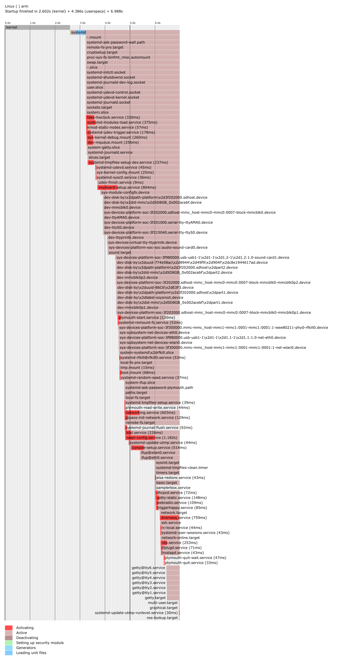
We love to listen to FIP, as it’s a public radio, without commercials and not so much speaking.
Unfortunately, this radio is FM brodcasted in only few city in France, and here in Grenoble, the only way to get is internet.
So we built this small kitchen radio, music playing in 14 seconds, and quite pleasantly aesthetic, in the same line as my previous nixie clock.
The large solid aluminium knob with amplifier pot ON/OFF produces a comforting click to power ON/OFF the device or adjust the volume.
The shiny stainless steel button is for future upgrade to allow changing from few radio as currently only one is available.
Hardware part
Here are almost all the items needed for this DIY hack:
- Ikea box (4€)
- 4″ coax speaker (scrap)
- 1″ tweeter (3€ on AE)
- Rpi 3b (40€ on Farnell)
- USB sound card (5€ on AE)
- Stereo 5V amplifier (1€ on AE)
- aluminium knob (5€ on AE)
- stainless steel push button (1€ on AE)
- C5 pannel connector for main supply (0.1€ on AE)
- USB wall wart (scrap)
- piece of 5mm plywood (scrap)
- speaker fabric for front pannel (4€ on AE)
- 30cm of leather belt (scrap)
- washed nuts (1€ on AE)
A total of about 60€
Step by step assembly
Let’s remove the USB sound card along with the extra not needed capacitors and jack connector (desoldering station is realy a must here)
Make a slot for the micro SD card on the back: remember, the Wifi credential are stored here.
A XY table on a drill press was usefull, I didnt imagine bamboo being so hard to mill.
Piece of leather bought in Texas, this is what’s left from my buckle-less belt I made few years ago, it could be an entry someday.
With the washer nuts, it look nice.
The C8 pannel connector, wired to the wall wart.
Everything fitted in the box, held in place with double side tape (the brand Multicomp from Farnell is nice).
Adhesive rubber feet add an extra touch.
Piece of plywood for the front panel, black mate painted, with the speaker cloth.
Held in place with thin double side tape.
Finish
Let’s add a small tag to give some identity to this yet unbranded product. A nice friendly name, with our initials to personalize it even more.
Warm up kicad and start just a PCB without schematics, with a beveled edge to add a touch of design:
The result is very good, with this mirror finish!
Once glued on the product, it does raise the bar. (a pitty the manufacturing reference is on the front, next time I’ll do my artwork on the back, just to make sure it’s not on the front)
A quick video:
Software part
Download RPI image
Download a RPI image, in this case, I choose : pipaOS A lighweight, fast, Raspbian based distro for the Raspberry PI
Once the image unziped, copy to a fresh high performance micro SD card
sudo dd bs=4M if=./pipaos-tamarillo-4.7.img of=/dev/mmcblk0
in order to boost performances, I use a Samsung EVO+ for high performance for a very fast boot
ssh sysop@192.168.1.84 (password posys)
Connect to WIFI network
Rpi 3 rev B and Zero W have integrated wifi
Edit WIFI credentials
The file /etc/network/interfaces should NOT be modified, as it’s overwritten at start.
Edit the file
sudo nano /boot/network.ini
To add your credential:
#
 # interfaces - setup your networking devices here
 #

auto lo
 iface lo inet loopback

allow-hotplug eth0
 iface eth0 inet dhcp

allow-hotplug usb0
 iface usb0 inet dhcp

# pipaOS Will automatically try to connect
 # to wireless ESSID "pipaos" passphrase "pipa123pass"
 allow-hotplug wlan0
 iface wlan0 inet dhcp
 wpa-ssid YOUR_SSSID
 wpa-psk YOUR_WIFI_KEY
High quality sound
Rasberry Pi have 3.5mm stereo jack output but the quality is pure crap, wondering why they even bother populate a jack.
So lets connect a cheap UBS sound card and check what appends
dmesg
sould display something like
[ 106.865142] usb 1-1.2: new full-speed USB device number 5 using dwc_otg
 [ 107.006372] usb 1-1.2: New USB device found, idVendor=0d8c, idProduct=0102
 [ 107.006387] usb 1-1.2: New USB device strings: Mfr=0, Product=2, SerialNumber=0
 [ 107.006395] usb 1-1.2: Product: USB Sound Device

[ 107.042816] input: USB Sound Device as /devices/platform/soc/3f980000.usb/usb1/1-1/1-1.2/1-1.2:1.3/0003:0D8C:0102.0002/input/input1
 [ 107.105630] hid-generic 0003:0D8C:0102.0002: input,hidraw0: USB HID v1.00 Device [USB Sound Device ] on usb-3f980000.usb-1.2/input3
and
lsusb
will output:
 Bus 002 Device 009: ID 0d8c:0102 C-Media Electronics, Inc. CM106 Like Sound Device
 Bus 002 Device 001: ID 1d6b:0002 Linux Foundation 2.0 root hub
 Bus 001 Device 001: ID 1d6b:0002 Linux Foundation 2.0 root hub
Create startup service : webradio
sudo apt-get install mplayer
mplayer `curl -w "%{url_effective}\n" -I -L -s -S http://direct.fipradio.fr/live/fip-midfi.mp3 -o /dev/null`
Webradio player script
create non returning script:
sudo nano /home/sysop/webradio.sh
while true
 do mplayer http://chai5she.cdn.dvmr.fr:80/fip-midfi.mp3
 sleep 1
 done
create init.d service: webradio
#!/bin/bash
 #webradio daemon
 # chkconfig: 345 20 80
 # description: mwebradioapp daemon
 # processname:webradio

DAEMON_PATH="/"

DAEMON=/home/sysop/webradio.sh
 DAEMONOPTS=""

NAME=myapp
 DESC="My daemon description"
 PIDFILE=/var/run/$NAME.pid
 SCRIPTNAME=/etc/init.d/$NAME

case "$1" in
 start)
 printf "%-50s" "Starting $NAME..."
 cd $DAEMON_PATH
 PID=`$DAEMON $DAEMONOPTS > /dev/null 2>&1 & echo $!`
 #echo "Saving PID" $PID " to " $PIDFILE
 if [ -z $PID ]; then
 printf "%s\n" "Fail"
 else
 echo $PID > $PIDFILE
 printf "%s\n" "Ok"
 fi
 ;;
 status)
 printf "%-50s" "Checking $NAME..."
 if [ -f $PIDFILE ]; then
 PID=`cat $PIDFILE`
 if [ -z "`ps axf | grep ${PID} | grep -v grep`" ]; then
 printf "%s\n" "Process dead but pidfile exists"
 else
 echo "Running"
 fi
 else
 printf "%s\n" "Service not running"
 fi
Install startup service
update-rc.d webradio defaults
Start service manually
sudo service webradio start
Check startup time and performance
Startup time with RPI 3 B: Startup finished in 2.602s (kernel) + 4.386s (userspace) = 6.988s
Not bad at all for a full featured computer with wifi and usb audio
Create the file:
.local/share/nemo/actions/thunderbird.nemo_action
Just cut and paste this inside that file and you’re done 
[Nemo Action]
Name=Send by Email
Comment=Send by Email the files
Exec=thunderbird -compose to=,"attachment='%U'"
Icon-Name=thunderbird
Selection=notnone
Extensions=nodirs;
Separator=,
EscapeSpaces=false
]]>
Create the file:
.local/share/nemo/actions/thunderbird.nemo_action
Just cut and paste this inside that file and you’re done
[Nemo Action]
Name=Send by Email
Comment=Send by Email the files
Exec=thunderbird -compose to=,"attachment='%U'"
Icon-Name=thunderbird
Selection=notnone
Extensions=nodirs;
Separator=,
EscapeSpaces=false
]]>
Easy procedure to reset toner counter: open the top cover, hold the * button for 5 sec (beside to keypad, not back-lighted, you can barely see it).
A reset menu appears and voila!
Fuck you Brother! My toner don’t need to be changed, my next printer wont be one of yours.
]]>
Easy procedure to reset toner counter: open the top cover, hold the * button for 5 sec (beside to keypad, not back-lighted, you can barely see it).
A reset menu appears and voila!
Fuck you Brother! My toner don’t need to be changed, my next printer wont be one of yours.
]]>
 Télécharger le PDF ici
]]>
Télécharger le PDF ici
]]>
Télécharger le PDF ici
]]>
Télécharger le PDF ici
]]>
 ]]>
]]>
]]>
]]>
This very simple tool, xbanish, hide mouse’s cursor away when you start typing, and is restored back when moving the mouse.
]]>This very simple tool, xbanish, hide mouse’s cursor away when you start typing, and is restored back when moving the mouse.
]]>
]]>“My world is full of small frustrations like this. For example, most customers perceive plastics with a mirror finish to be of a higher quality than those with a satin finish. There is no functional difference between the two plastics’ structural performance, but making something with a mirror finish takes a lot more effort. The injection-molding tools must be pains-takingly and meticulously polished, and at every step in the factory, workers must wear white gloves. Mountains of plastic are scrapped for hairline defects, and extra films of plastic are placed over mirror surfaces to protect them during shipping. For all that effort, for all that waste, what’s the first thing users do? They put their dirty fingerprints all over the mirror finish. Within a minute of a product coming out of the box, all that effort is undone. Or worse yet, the user leaves the protective film on, resulting in a net worse cosmetic effect than a satin finish. Contrast this to satin-finished plastic. Satin finishes don’t require protective films, are easier for workers and users to handle, last longer, and have much better yields. In the user’s hands, they hide small scratches, fingerprints, and bits of dust. Arguably, the satin finish offers a better long-term customer experience than the mirror finish. But that mirror finish sure does look pretty in photographs and showroom displays!”
]]>“My world is full of small frustrations like this. For example, most customers perceive plastics with a mirror finish to be of a higher quality than those with a satin finish. There is no functional difference between the two plastics’ structural performance, but making something with a mirror finish takes a lot more effort. The injection-molding tools must be pains-takingly and meticulously polished, and at every step in the factory, workers must wear white gloves. Mountains of plastic are scrapped for hairline defects, and extra films of plastic are placed over mirror surfaces to protect them during shipping. For all that effort, for all that waste, what’s the first thing users do? They put their dirty fingerprints all over the mirror finish. Within a minute of a product coming out of the box, all that effort is undone. Or worse yet, the user leaves the protective film on, resulting in a net worse cosmetic effect than a satin finish. Contrast this to satin-finished plastic. Satin finishes don’t require protective films, are easier for workers and users to handle, last longer, and have much better yields. In the user’s hands, they hide small scratches, fingerprints, and bits of dust. Arguably, the satin finish offers a better long-term customer experience than the mirror finish. But that mirror finish sure does look pretty in photographs and showroom displays!”
4 years after the previous article, I still need this tool, but I wanted a more “natural” TTS.
So I’m using Voxygen, a natural TTS provider (very good for French), retrieving the generated voice with wget and the following command:
wget --quiet --no-check-certificate -O /tmp/clock_`date +\%-1H`.mp3 "https://www.voxygen.fr/sites/all/modules/voxygen_voices/assets/proxy/index.php?method=redirect&text=il est exactement `date +\%-1H` heures.&voice=Loic"
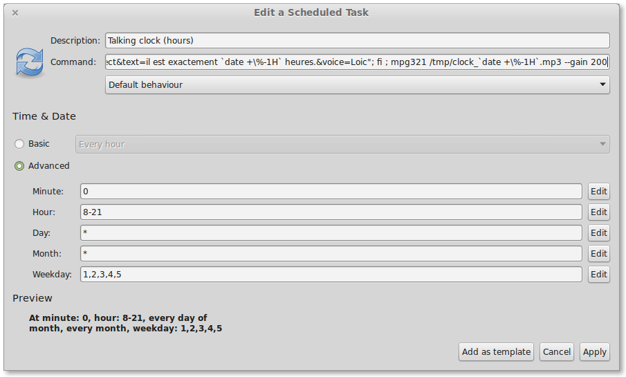
Here is the script to run every hours:
if [ ! -e /tmp/clock_`date +\%-1H`.mp3 ]; then wget --quiet --no-check-certificate -O /tmp/clock_`date +\%-1H`.mp3 "https://www.voxygen.fr/sites/all/modules/voxygen_voices/assets/proxy/index.php?method=redirect&text=il est exactement `date +\%-1H` heures.&voice=Loic"; fi ; mpg321 /tmp/clock_`date +\%-1H`.mp3 --gain 200
We will be using gnome schedule taks:
4 years after the previous article, I still need this tool, but I wanted a more “natural” TTS.
So I’m using Voxygen, a natural TTS provider (very good for French), retrieving the generated voice with wget and the following command:
wget --quiet --no-check-certificate -O /tmp/clock_`date +\%-1H`.mp3 "https://www.voxygen.fr/sites/all/modules/voxygen_voices/assets/proxy/index.php?method=redirect&text=il est exactement `date +\%-1H` heures.&voice=Loic"
Here is the script to run every hours:
if [ ! -e /tmp/clock_`date +\%-1H`.mp3 ]; then wget --quiet --no-check-certificate -O /tmp/clock_`date +\%-1H`.mp3 "https://www.voxygen.fr/sites/all/modules/voxygen_voices/assets/proxy/index.php?method=redirect&text=il est exactement `date +\%-1H` heures.&voice=Loic"; fi ; mpg321 /tmp/clock_`date +\%-1H`.mp3 --gain 200
We will be using gnome schedule taks:

Made of:
- DC/DC buck boost converter (3€ on ebay)
- USB battery pack 5€
- scrapped fan
- scrapped switch
- scrapped potentiometer
- Hammond prototype case (1€, same as my USB motion sensor)
- nice labels
- double side tape
Enough talk, a picture:

And in action, can suck up to 15cm at medium speed:

This “hack” took me 30min, and costs close to nothing, while some have been down to build a DC/DC converter for this!
Thing to add in the future:
- active carbon filter for better filtering, but usable as is for small jobs: you don’t get fumes in your face anymore.
- USB light for soldering in the dark
My favourite use: in the freezer/fridge, when you forgot to chill beers for an unexpeted party, it takes only 10min to have freezing beer instead of 1h. (remove the carbon filter first…)
]]>
Made of:
- DC/DC buck boost converter (3€ on ebay)
- USB battery pack 5€
- scrapped fan
- scrapped switch
- scrapped potentiometer
- Hammond prototype case (1€, same as my USB motion sensor)
- nice labels
- double side tape
Enough talk, a picture:
And in action, can suck up to 15cm at medium speed:
This “hack” took me 30min, and costs close to nothing, while some have been down to build a DC/DC converter for this!
Thing to add in the future:
- active carbon filter for better filtering, but usable as is for small jobs: you don’t get fumes in your face anymore.
- USB light for soldering in the dark
My favourite use: in the freezer/fridge, when you forgot to chill beers for an unexpeted party, it takes only 10min to have freezing beer instead of 1h. (remove the carbon filter first…)
]]>