I have an always on net-book for weather forecast (yeah, when paragliding, you need the most up to date forecast)
It basically displays a full screen custom web-page with time and date and weather.

Its always on, not really good for the back-light and energy consumption.
So I got the idea of plugging a PIR sensor to wake up the screen when someone approach it.
 Take an Arduino Micro Pro (4€ for the Chinese version), a PIR sensor (2€), a Hammond case (1€) and an USB A male from scrap (0€).


Let’s give a try, with a basic wiring, and this sketch to emulate keyboard thanks to it’s USB HID, the Arduino Micro Pro is a must.
Updated 05-01-2017:
- code with USB wakeuphost and capslock instead of ctrl
- green TX led always on
- orange RX led only on motion
#include <Keyboard.h>

#define SENSOR_PIN 10   // Senor state input pin
#define RX_LED_PIN  17  // The RX LED has a defined Arduino pin
static bool sensor_previous_state = false;

void setup()
{
  pinMode(SENSOR_PIN, INPUT);  // PIR sensor pin as input
  pinMode(RX_LED_PIN, OUTPUT);     //  RX LED as an output
  digitalWrite(RX_LED_PIN, HIGH);  //  RX LED off
  TXLED0;                     // switch on TX green to show init/powered up (only available by macro)
  sensor_previous_state = digitalRead(SENSOR_PIN); // get sensor initial state (can be already true)
}

void loop()
{
  bool sensor_current_state = digitalRead(SENSOR_PIN);
  if ( sensor_previous_state == false   // looping until we detect a rising edge
       && sensor_current_state == true) {// when sensor state is trigged, it takes about 20 sec to recover
    digitalWrite(RX_LED_PIN, LOW);   // set the LED on
    USBDevice.wakeupHost();
    Keyboard.press( KEY_CAPS_LOCK );
    Keyboard.release( KEY_CAPS_LOCK );
    TXLED0;                     // great hackery in this: we have to force down the TXLED
    delay(1000);                  // wait a bit for the led
  } else {
    digitalWrite(RX_LED_PIN, HIGH);    // set the LED off
    TXLED0;
  }
  sensor_previous_state = sensor_current_state;
}


 2017 update: lightguide for green and orange LEDs:
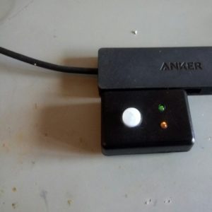
Update: LED lightguides from the scrap box
And voila!

Quite nice, discrete and works very well, for about 10€/$.
This is really great! What are the wiring schematics though? I want to build this so I want to be sure to get this right. Thanks.
Updated with schematics for dummy, 3 wires, will you handle?
As ive only played with the rpi and uno r3 I had no idea the pro was hid! lol.
Have you worked out the solution as to stop it pressing ctrl constantly?
Thanks
This is great stuff. I have used your guide to create my own usb motion sensor. This is to wake my kitchen touchscreen. I have also updated the USBCore.h and script slightly to also support walking the pc when it’s asleep.
More details on my blog
http://digitalgeek.me/blogview.php?id=29
I don’t want to build one. I want to buy one. How much?
Sure, I can sell you this unit: $95 including shipping worldwide.
Hi,
I notice in your Schematic drawing no additional resistor but there is in the image above it.
Is the additional Resistor a requirement?
Regards
Steve
The resistor is optional, but it’s always nice to put one (from 10ohm to 1k), to adapt impedances and limit current.
I’m planning something similar to this, using 4 separate sensors for 4 different keystrokes, but I’m a complete novice. would a single pro micro suffice for all 4 sensors?
Sure, with 4 inputs, and 4 keystroke, will work.
Hi. Just want to ask if you can create a micro sensor that beeps or blinks a led llight when someone is approaching or coming near on the sensor about 1 to 2 meters? Please email me if you can create this one. Very Interested.
Thank you.
Vener
Sure, it’s quite easy to make, as a proof of concept, no problem.
But if you need something, low power, reliable, and you are not an EE, then go to Amazon buy a end product
Hello,
Do you know any commercial product that does exactly this (emulate keyboard input on motion detection)? I need many of these so doing them is not really an option. Thanks!
Gnagnu
Nope, I’m not aware of similar “USB PIR sensor” as commercial product. Otherwise I would have bought one instead of spending 2hours hacking it.
You can request a design on freelancer.com and find a company such seedstudio to manufacture it.
If you find one, don’t hesitate to post it here.
Good job. Here is one with a broken mouse and getting the clics of it. http://openwrt.tuinstituto.es/sensor-de-movimiento-pir-conectado-a-un-raton-usb
Since I happened to have issues with keyboard states, I changed to use mouse movements. If i had no-zero (e.g. 10) mouse movements, they were easy to see in Windows for debugging. I found that mouse movements of zero still trigger Windows. I also toggle the Pro Micro TX LED when motion is detected. Code:
#include Mouse.h
int sensorPin = 10;
void setup()
{
pinMode(sensorPin, INPUT);
Serial.begin(9600);
}
void loop()
{
if (digitalRead(sensorPin) == 1)
{
TXLED1; // Turn on TX LED to indicate movement
Mouse.move(0, -0);
delay(100);
Mouse.move(0,0);
delay(100);
TXLED0; // Turn off TX LED
}
}
@kiwin: thanks for your snipet!
Pingback: Portable soldering fumes extractor fan DIY (battery operated and rechargeable) | DotMana
I am looking to purchase some of these. Can you let me know how I can order?
Sure, but as I previously said, as it’s hand made, it’s rather expensive, are you willing to buy anyway?
hello, Total newbie question here, where do you put the code that you have written above? Do you program the board or does it run on your computer?
Thanks!
That’s the Arduino code, have a look on the Arduino page.
Hi Tweepy
I’m trying to do copy your project, but with the Arduino UNO instead, do you know if it will run?
No it wont work: you need an arduino model with the USB HID stack running.
For a key to wake you could try using F13, there exist key codes all the way up to F24 but they do nothing so they should be perfect for this.
Hi Tweepy,
I’ve used your latest code (5 Jan 2017) with two new Arduino Micro Pro initially in good working order, but after loading the sketch got a desktop warning “USB device not recognised”, and in the Device Manager / USB Controllers folder the board appears now as “Unknown USB Device (Device Descriptor Request Failed)”.
Both boards are frozen now in this state and all my attempts to reset them failed.
Any idea what possibly went wrong, and what can I do to fix it.
Many thanks, George
Win 10 V1703, Arduino 1.8.1
Hi George, thanks for your message. I’m not sure to be able to help you as I’m only on linux desktop, not Windows.
But from my limited knowledge of the Arduino plateform, it appears the Micro Pro doesn’t have a dedicated programmer as the UNO or other model, but uses the main CPU as bootloader at startup then launches your sketch.
When fiddling with this Micro Pro, I found out that when your software overflows or crash, it reboots in loop and never gives you access to the bootloader to reupload a new sketch. To workaournd this, with a wire, connect RST and GND, then upon releasing, hit Upload sketch. While tricky, it seems to work for me.
Thanks for your reply, Tweepy.
I have another machine around running Ubuntu. Are you suggesting that it might be easier to salvage these two boards on that machine?
No, I’m not saying that, Windows should be fine, it’s just you have to make an hardware reset with the RST pin just before uploading the sketch.
I’ve tried this several times before writing to you, but didn’t work. The USB error message disappears for a couple of seconds, but in this time the USB port on Arduino IDE stays greyed out so nothing can be uploaded.
Hi Tweepy,
I’ve managed to load the sketch, the CTRL-key is pressed and released at motion (I can see it on the on-screen keyboard) but the computer doesn’t wakeup. BTW the computer wakes up when the CTRL key is pressed on the physical keyboard.
Any ideas why is this happening? Many thanks, George
I’m trying to build this project and it’s my first attempt at Arduino (sorry). I have realised that the board I purchased is the “Nano” not the “Micro Pro”. In my googling I’m having trouble determining if the Nano should be able to suit this project. The problem I am having is “‘USBDevice’ was not declared in this scope” which could be either it is not supported by the Nano or that I have some newbie library/programming error. Do you know if the Nano should be capable?
The Nano is not compatible: it’s not a USB capable microcontroller.
As specified in the article you need a Micro Pro. The Arduino Micro Pro has direct USB connectivity and don’t use a serial/USB adapter for programing/communication. When it works, it’s great but when buggy, because of the USB stack used in the bootloader for reprogramming, sometimes it can be a pain and a pair of tweezers for multiple reset are handy for recovery.
Hi Tweepy,
Apparently i reinvented the wheel… Maybe someone finds my motion sensor design helpful:
https://www.thingiverse.com/thing:2893684
Indeed, thanks for sharing.
Hi! I’m wondering if it is possible to make this inversely. So the sensor is on, but when motion is detected turns off. Would it be possible?
This gadget sends a computer some even to wake it up.
How do you imagine the opposite? Send an event to shutdown/suspend/lock screen?
To lock the screen on PIR activity (win/mac key + L):
#include
#define PIR_PIN 6 // PIR signal input pin
void setup()
{
pinMode( PIR_PIN, INPUT ); // PIR sensor pin as input
digitalWrite( LED_BUILTIN, LOW );
}
void loop()
{
if ( digitalRead( PIR_PIN ) )
{
digitalWrite( LED_BUILTIN, HIGH );
Keyboard.press( KEY_LEFT_GUI );
Keyboard.press( ‘l’ );
delay(100);
Keyboard.releaseAll();
delay(5000);
digitalWrite( LED_BUILTIN, LOW );
}
delay(200);
}
Awesome, thanks for the tip!
Hi All.
Initially may I say thanks to all that have created this project and posted incredibly great information on where to get the necessary equipment etc.
This is my first attempt at constructing an Arduino or anything like it and definitely my first attempt at any type of coding. I have watched hours of YouTube and read Gigabytes of information and have had a great time doing so.
However, I have come to a screaming halt with this project. I have managed to construct it and install the Arduino software and managed to flash the coding to it successfully. But unfortunately, that is where the success stops.
I get a message as shown below via the Windows 10 64bit computer in Device Manager – Arduino Leonardo Properties.
Device USB\VID_2341&PID_8036&MI_00\6&1b780c72&0&0000 requires further installation.
I have tried in vain to find a solution, but I am struggling to make sense of it or come up with a way to make it work.
I am hoping someone will have the answer for this and fingers crossed, it will be an easy simple fix for someone with extremely limited experience like me?
The other issue I have is that the coding and explanation with the updated 2017 version as mentioned in a previous post by the creator of this project is the addition of a green and a yellow LED. I have all the LEDs and cabling etc. but am unsure as to what terminals to attach the LEDs to? I know it is blatantly obvious to some of you reading this, but I would sooner ask the obvious question avoiding the chance of damaging anything.
Any assistance or advice to a complete novice would be gratefully be received so I can finally get this working. Many thanks in advance.
Kindest regards.
About your Windows issue, have a look at a tutorial how to make your development board works before going any further.
For the LED, they are RX and TX LED, already present on the Arduino Micro Pro, you cannot access them directly, that’s why you need to use TXLED0. But good news, you can connect it to any GPIO and use the digitalWrite(RX_LED_PIN, HIGH); to set it HIGH or LOW
Arduino: 1.8.13 (Windows 10), Board: “Sanguino, ATmega644 or ATmega644A (16 MHz)”
C:\Users\cowbo\AppData\Local\Temp\arduino_modified_sketch_377798\sketch_sep10a.ino: In function ‘void setup()’:
sketch_sep10a:12:3: error: ‘TXLED0’ was not declared in this scope
TXLED0; // switch on TX green to show init/powered up (only available by macro)
^~~~~~
C:\Users\cowbo\AppData\Local\Temp\arduino_modified_sketch_377798\sketch_sep10a.ino:12:3: note: suggested alternative: ‘TXEN0’
TXLED0; // switch on TX green to show init/powered up (only available by macro)
^~~~~~
TXEN0
C:\Users\cowbo\AppData\Local\Temp\arduino_modified_sketch_377798\sketch_sep10a.ino: In function ‘void loop()’:
sketch_sep10a:22:5: error: ‘USBDevice’ was not declared in this scope
USBDevice.wakeupHost();
^~~~~~~~~
sketch_sep10a:23:5: error: ‘Keyboard’ not found. Does your sketch include the line ‘#include ‘?
Keyboard.press( KEY_CAPS_LOCK );
^~~~~~~~
sketch_sep10a:23:21: error: ‘KEY_CAPS_LOCK’ was not declared in this scope
Keyboard.press( KEY_CAPS_LOCK );
^~~~~~~~~~~~~
sketch_sep10a:25:5: error: ‘TXLED0’ was not declared in this scope
TXLED0; // great hackery in this: we have to force down the TXLED
^~~~~~
C:\Users\cowbo\AppData\Local\Temp\arduino_modified_sketch_377798\sketch_sep10a.ino:25:5: note: suggested alternative: ‘TXEN0’
TXLED0; // great hackery in this: we have to force down the TXLED
^~~~~~
TXEN0
sketch_sep10a:29:5: error: ‘TXLED0’ was not declared in this scope
TXLED0;
^~~~~~
C:\Users\cowbo\AppData\Local\Temp\arduino_modified_sketch_377798\sketch_sep10a.ino:29:5: note: suggested alternative: ‘TXEN0’
TXLED0;
^~~~~~
TXEN0
exit status 1
‘TXLED0’ was not declared in this scope
What am I missing here? When I try to upload I get these errors….
Look like you are using a Arduino without USB stack, make sure to use a Micro Pro or other with native USB
Yes you are correct! After doing some research [which I should have done to start with] I would have purchased the right microcontrollers LOL I ordered the correct ones with USB communication. THANK YOU!
As soon as they get here I’ll be back on track! Great project!
You are welcome, please drop a message or picture once your project finished!
Well I did get the code on both the Ardunio Micros…. problem for me is the wiring… I know ground is ground but using an actual Ardunio not sure where the other two wires connect to…. Sorry to be such a pain but I’m so close LOL
Well the only other thing I didn’t take into account is that I bought actual Arduino Micros and the wiring is different. Being new to this I am a bit lost. I did find the ground but the other two wires…. If you could help me out that would be great! The other thing is can I do this without changing the code? Thank you so much for helping!
Simply connect the wire to the correct pin, they are only, 3 of them: GND to GND, VCC to VCC, and the PIR output to a GPIO, in this code, it’s GPIO number 10.
Sorry about the double post but Thank you for help! Had to ‘play’ a little as my PIR isn’t labeled but I got it! I’ll post a picture when it’s done!
I thought I could post a pictures but I’ll just have to tell you about the project.
I’m currently running Home Assistant on a 32″ touch screen. The ‘brains’ is a mini-itx and I couldn’t hardwire a pir like I could a Pi3 so this was the best option!
It’s running on Unbuntu with xscreensaver to blank the screen after 1 minute of no activity. I plugged this in and right off the bat it’s working like a charm!!!
I also have a ‘mirror’ in the bathroom that mirrors the main screen but the PIR sensor is not working on that one for some reason. I need to touch the spacebar on the keyboard to show the screen :(. That one is running on an old laptop board….. not sure why it’s not working but I’m sure there’s a way to get it to work….. even if I hit the ctrl key it comes back on so that’s not the issue.
It’s like the board isn’t accepting the ‘key stroke’ via USB.
Thank you so much for all the help!!! My main goal is accomplished Thanks to you!!!