USB-C iron solder: TS100

TS100 is a very good iron solder, with a rated power of 17 to 65W, when powered from 12 to 24V.

While 12V DC jack DC5525 are everywhere, 24V are less but needed if you want more heat to solder larger components or grounds. (better than the TS-80 with the weak 18W anyway)

Supplying from USB-C source with PD 19V 60W takes full advantage of this iron solder.

This hack has been made but not robust enough nor slick to my taste.

This 3 bucks USB-C to DC5.5mm @19V does the job.

Here a RAVPower 60W PD is used

Perfect for my mobile bench with the classic DPS3005 power supply.

Mini portable power supply DIY

Here is a small DIY project, for a portable/bench-top power supply. We are not aiming for the best regulation, neither most power. But portability and bench-top estate optimisation.

This is based on the famous DPS3005 (about 25€)

Let’s 3D print an enclosure, found on Thingiverse:

And grab all the jelly beans needed:

Wire/crimp/solder:

Does work quite well:

With not much noise (static 100mA load):

And as I’ve this fancy portable solder iron with a bunch of li-ion cell:

It works on the road!

microSD card reflow: quick and dirty PCB with Kicad

Ever wanted to add a lot a flash memory to a small microcontroller? NOR flash or EEPROM are ok, but only for small size. For Gbit range, you need NAND, and with NAND comes CCR, LUT, wearleveling, etc… Furthermore, they are darn expensive in small volume.

SD and microSD card are very interesting: they cost nothing, and you just need a SPI interface as the controller is included.

Last night, I thought: “why not reflow a complete microSD card”, and save the cost of the socket, and PCB footprint size. As the card is composed of the same resin as chip casing and pins are flat bellow the microSD card and even gold plated, fore sure it should not be a problem to bring this to 270°C for 2-3 min….

Let’s try!

Here is the pinout

Then let’s create a small board, to try the reflow of a micro SD card and give access with some 2.54mm header.

Lets open Kicad and start with the schematic with Eeschema:

Then PCB new for the board layout:

MicroSD footprint and module for Kicad: microSD_Card

Let’s submit the gerber files to, you can order the board here (shared project): OSH Park

Total including USPS post mail: 4.10€

That was my fastest board made ever, 1h30 from searching the pinout to the confirmation email!

See you back in few week for the oven reflow test!

Update: the board and the reflow!

First, let’s clean it and apply some flux:

Then some solder on the pads, and flux again:

Time to turn the heating plate and IR reflow on:

Just stir it a bit while it’s hot:

Houston, we have a reflow!

Then time to test: lets scavenge a super cheap reader microSD card reader:

And plug it: IT WORKS! After 3 min under the IR station, it does work.

I think I’ve to increase the pad size, in order to maximize the solder paste.

Now I’m confident sending to production, as I’ve quite a lot of theses cards in trays, ready for pick and place:

USB motion sensor (PIR) to activate monitor

I have an always on net-book for weather forecast (yeah, when paragliding, you need the most up to date forecast)
It basically displays a full screen custom web-page with time and date and weather.

Its always on, not really good for the back-light and energy consumption.

So I got the idea of plugging a PIR sensor to wake up the screen when someone approach it.

Take an Arduino Micro Pro (4€ for the Chinese version), a PIR sensor (2€), a Hammond case (1€) and an USB A male from scrap (0€).

Let’s give a try, with a basic wiring, and this sketch to emulate keyboard thanks to it’s USB HID, the Arduino Micro Pro is a must.

Updated 05-01-2017:

  • code with USB wakeuphost and capslock instead of ctrl
  • green TX led always on
  • orange RX led only on motion
#include <Keyboard.h>

#define SENSOR_PIN 10   // Senor state input pin
#define RX_LED_PIN  17  // The RX LED has a defined Arduino pin
static bool sensor_previous_state = false;

void setup()
{
  pinMode(SENSOR_PIN, INPUT);  // PIR sensor pin as input
  pinMode(RX_LED_PIN, OUTPUT);     //  RX LED as an output
  digitalWrite(RX_LED_PIN, HIGH);  //  RX LED off
  TXLED0;                     // switch on TX green to show init/powered up (only available by macro)
  sensor_previous_state = digitalRead(SENSOR_PIN); // get sensor initial state (can be already true)
}

void loop()
{
  bool sensor_current_state = digitalRead(SENSOR_PIN);
  if ( sensor_previous_state == false   // looping until we detect a rising edge
       && sensor_current_state == true) {// when sensor state is trigged, it takes about 20 sec to recover
    digitalWrite(RX_LED_PIN, LOW);   // set the LED on
    USBDevice.wakeupHost();
    Keyboard.press( KEY_CAPS_LOCK );
    Keyboard.release( KEY_CAPS_LOCK );
    TXLED0;                     // great hackery in this: we have to force down the TXLED
    delay(1000);                  // wait a bit for the led
  } else {
    digitalWrite(RX_LED_PIN, HIGH);    // set the LED off
    TXLED0;
  }
  sensor_previous_state = sensor_current_state;
}
2017 update: lightguide for green and orange LEDs:
p70105-114417
Update: LED lightguides from the scrap box
And voila!
Quite nice, discrete and works very well, for about 10€/$.

Kobo mini GPS mod with 3D printed case

Introduction

XCSoar is an amazing software for sailplane, hang-glider and paraglider. But lack the proper hardware with the following features:

  • sun readable ( eink)
  • usable with gloves (anything but capacitive)
  • long battery life
  • running android/linux
  • GPS and/or bluetooth
  • dirt cheap (yes 50€/£/$ for this hardware is dirt cheap)

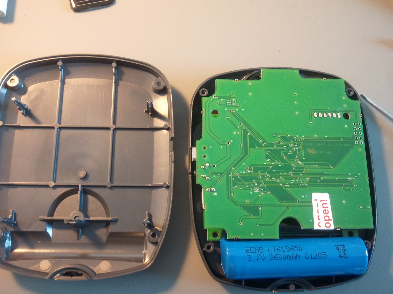
The Kobo Mini is a very good eReader (unfortunately no more retailed) appears to be meeting all theses requirements except the GPS.

Hardware

Component list

You will need for this mod:

  • Kobo Mini reader
  • GPS module with serial output or a BlueFlyVarioTTL
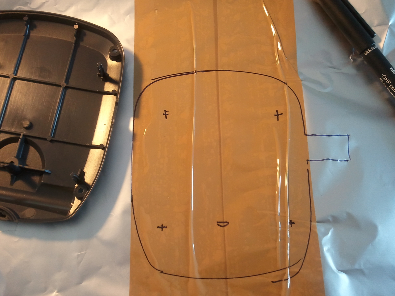
  • 3D printed spacer
  • extra battery
  • iron solder (a good one, I use this)
  • solder wire and a piece of flat ribbon cable

( By the way, the way Kobo handles the first boot is just crap: no I don’t want to register my device online or anything, just to drag and drop my own ePub books, thanks! )

GPS module instructions

Solder the MTK3339 GPS breadboard (with a piece of flat ribbon cable such as IDE, Floppy, whatever..)

KOBO to GPS MTK3339 wiring

KOBO - MTK3339
KVCC <-> VCC
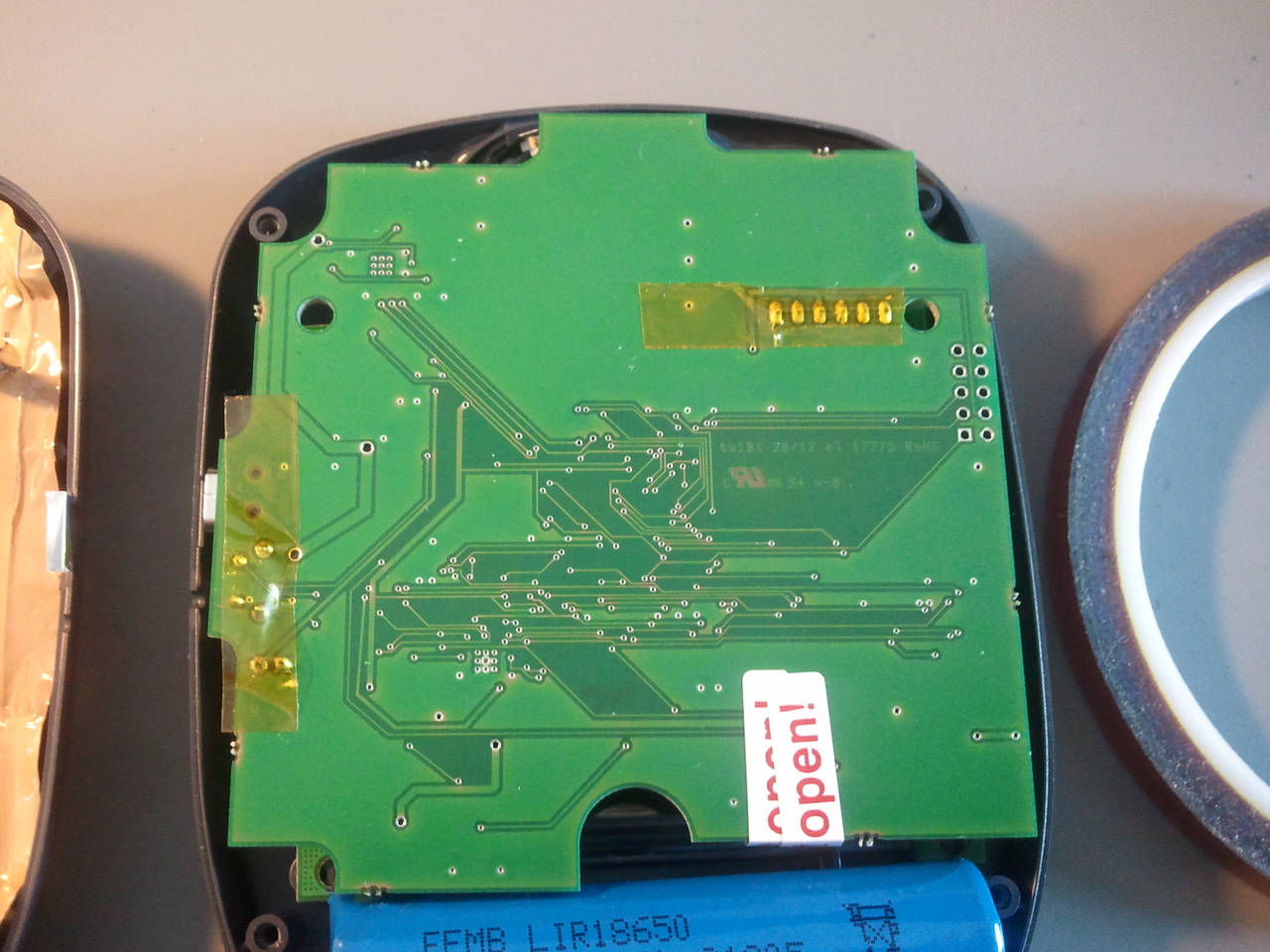
TP2 <-> BACKUP (TP2 is just below the battery connector)
RX  <-> TX
TX  <-> RX
GND <-> GND

Don’t forget to cross RX<->TX and TX<->RX (the eternal embedded engineer question, RX TX….)

Just in case you wondered, yes the BACKUP does accept 4.2V (TP2 is battery test point, so not regulated), and not just 3.3V (have a look on the MTK3339 datasheet)


You can download the STL of the “Kobo mini Case Spacer II” on Thingiverse

And download the gps cover

The STL (in mm) file is then printed by Shapeways for just 22€ incl P&P, delivered in about a week: very cool!


You will need 5screws, size M1.6 and 8mm (my 10mm were too long, I had to cut them with a pair of pliers)

All fit snugly, even the original back cover.

Add ON/OFF button to switch the GPS power (a simple SMD switch to the GPS’s VCC)

So I can still use it as a regular eBook without draining the battery and without the blue led blinking in the dark.

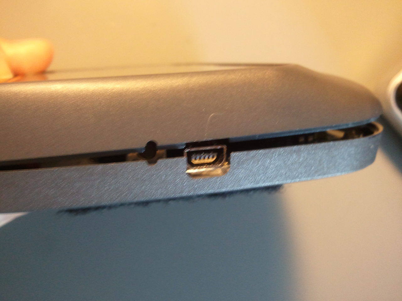
The switch is accessible by nails as it’s quite recessed.

Add a label for even more clarity.

BlueFlyVarioTTL instructions

Or this set for the BlueFlyVarioTTL, download the cover: And download the spacer for the battery:

The file STL (in mm) is then printed by Shapeways for just 19€.

You will need 5screws, size M1.6 and 8mm (my 10mm were too long, I had to cut them with a pair of pliers)

Solder 0.1″ header

And remove the black plastic from the header

Drill 5 holes with a 1mm bit, using the module as guide

Insert it

Then solder the 5 wires

Use 2 parker 3mm screws

That’s it

Battery for GPS module or BlueFlyVarioTTL

The original battery of 1000mAh gives from 4 to 6h, which can be quite a limitation.

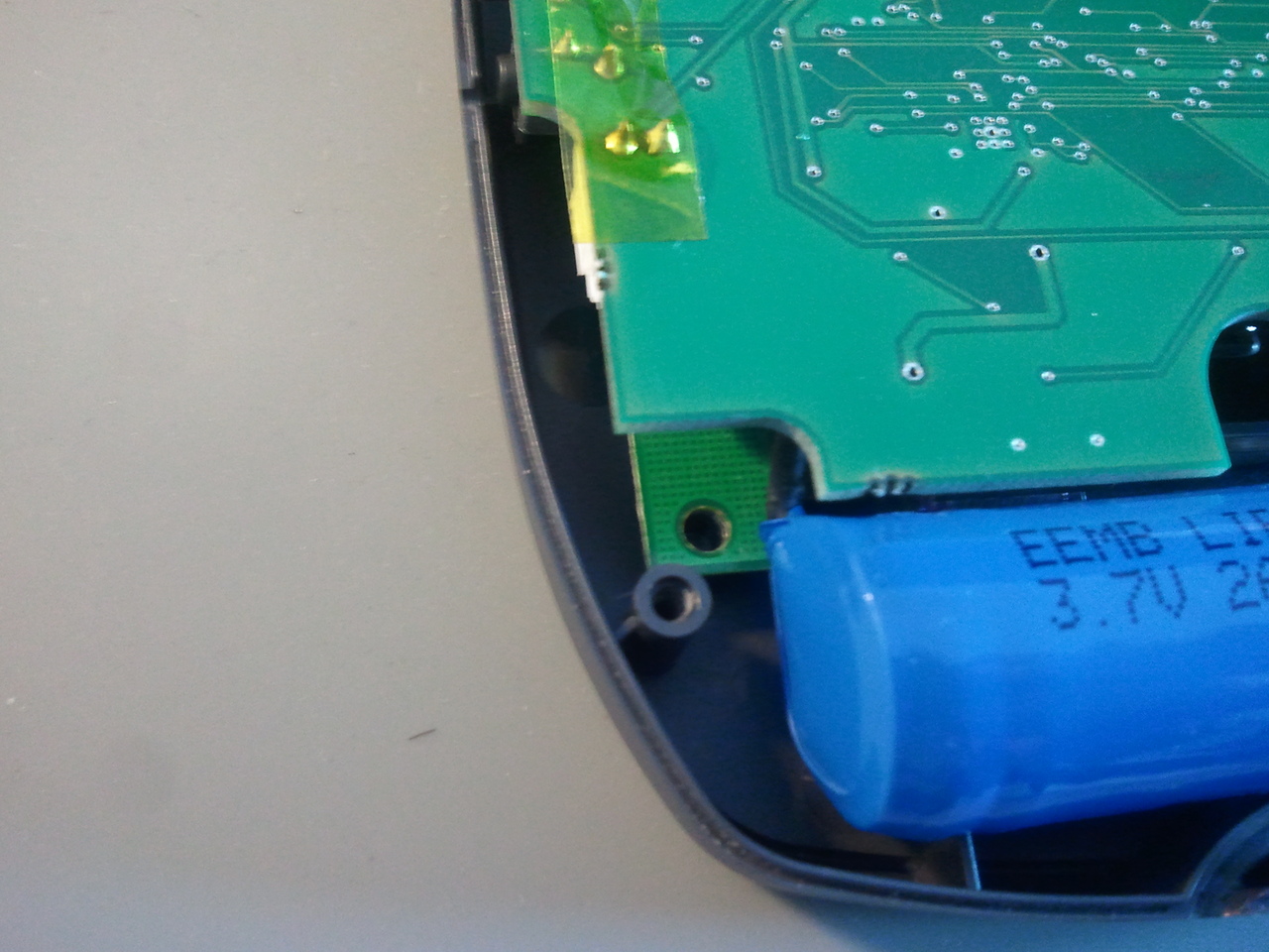
The original 1000mAh beside the new 3800mAh battery

The new battery li-ion from AliExpress measure 4x75x86mm, with 3.7V and 3800mAh. Warning, you need the 3D printed spacer to use this battery.

I removed the original one and harvested it’s connector for the new one.

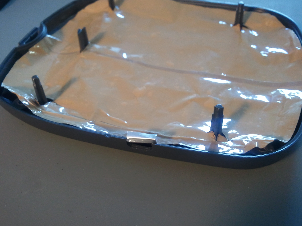
To remove the original double side taped battery, use an air dryer or so (warning not a hot air gun, it would be too hot)

The new battery is held firmly with double sided tape and now it last about 20hours of flight: perfect. (but the drawback: it is quite heavy to read in the bed now….)

Software

They are tons of tutorials on the web, I wont describe it any further, but simply put, it works this way:

Download XCSoar KoboRoot.tgz: http://www.xcsoar.org/download/data.html

And place it on the kobo root file system using any file browser, restart and you are done.

GPS configuration

GPS module

For the GPS module, set the device to /dev/ttymxc0 at 9600bauds, generic drivers.

BlueFlyVarioTTL

For the the BlueFlyVarioTTL, set the device to /dev/ttymxc0 at 57900bauds, blueflyvario drivers.

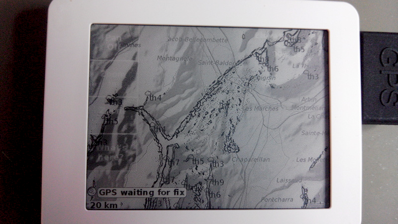
“GPS waiting for fix” should appear, note that the first fix can take up to 15min (30s later on, thanks to BACKUP power supply to keep the RTC and ephemeris)

You can change the sink alarm and volume:

  • Enable Wifi, and Telnet,
  • Connect to with telnet to the Kobo,
  • send the following commands:

stty ospeed 57600 ispeed 57600 -F /dev/ttymxc0 #configure baudrate

stty -F /dev/ttymxc0 raw #set device as raw

echo ‘$BFS 2500*’>/dev/ttymxc0 # sink alarm to -2500cm/s

echo ‘$BVL 70*’>/dev/ttymxc0 # volume to 70%


Maps

Then download the map: http://www.xcsoar.org/download/data.html

Download hotspot (probable thermal) as way-points (wpt format), and set the file in way-points configuration): http://thermal.kk7.ch/, save all this map file to the correct XCSoar folder.

I created custom map content to have paragliding skyways displayed on XCS:

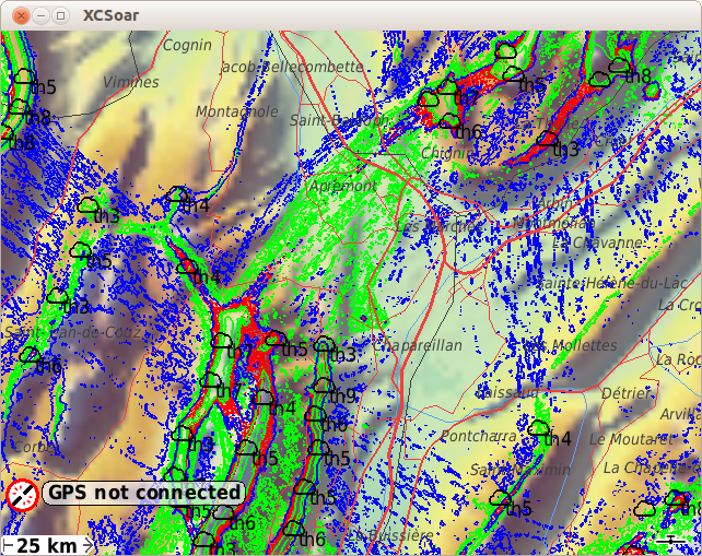
More detail here: http://www.dotmana.com/weblog/2014/07/xcsoar-generate-custom-maps/

And here you are, you have a comp GPS for less than 100€/$/£ for paragliding/sailplane, in about an hour of work.

Result with GPS module

Result with BlueFlyVarioTTL

(note the green led flashing when lifting)

leGPSBip: solar vocal GPS alti vario

This device is ready to use with the Kobo or any smartphone, simply connect it and voila! You have a fully GPS/altimeter enabled smartphone.

It also act as a standalone vocal GPS variometer when not connected, pretty convenient:

More info here: http://www.lebipbip.com/legpsbip-solar-vocal-gps-alti-vario/

Links and references

XCSoar forum: http://forum.xcsoar.org/viewtopic.php?f=3&t=1242

Kobo GPS mod on another blog: http://www.extreme-nature.de/?p=9114

M1.6×8 screws: http://www.ebay.co.uk/

Commercial Kobo mod: http://www.goflyinstruments.com/gofly-project-v4/

XCSoar forum about this mod: http://forum.xcsoar.org/viewtopic.php?f=3&t=1404&start=10

Li-ion battery on AliExpress: http://www.aliexpress.com/item/L002-3-7V-3800mAH-457992-PLIB-polymer-lithium-ion-battery-Li-ion-battery-for-tablet/1477811584.html

BlueFlyVarioTTL http://blueflyvario.blogspot.com.au/2014/11/blueflyvariottlgpsv10-released.html

BlueFlyVarioTTL case: http://blueflyvario.blogspot.com.au/2014/07/blueflyvariottlgps-simple-case.html

Mini Solar vario: http://www.lebipbip.com/

STL archive: Kobo_Mini_case

Why FLARM protects it’s radio protocol

The FLARM device is definitely useful for avoiding collision in sailplane.

But the company behind maintains it’s monopoly position arguing that’s it’s safer and cheaper for the users:

We fundamentally believe that our low cost collision warning technology and its licensing procedures are in the
best interests of the sport and its participants.

To ensure safety, full compatibility and interoperability are essential. Experience shows that it is impossible to
be compatible just by following a written specification.


This text is just regular company’s crap, to reassure themselves (and the shareholders) they can maintain a high level of monopoly (and profit).

They also state the radio protocol is patented:

FLARM applies for the radio communication between the units a proprietary and copyright-protected protocol

Unfortunately, there is no such thing as copyrighted radio protocol!

My prefered part is it when the founder respond this accusation of being obscure and avoid implementation in many hardware device, and in software such as XCSoar:

https://groups.google.com/d/msg/rec.aviation.soaring/daOXteD5ois/IJ1GTbxWPCAJ

The best part it: they managed to impose the device, not only in competition but for any sailplane in France. How comes the FFVV (French Gliding Federation) can make a device mandatory without any alternative?

One person, Hiram Yaeger seemed to have reverse engineered the protocol:

FLARM PROTOCOL VERSION 4 (2008)


If interoperability by documentation or standardization would not be possible, even in RF, there would be no GSM, no GPRS, no WIFI, no Bluetooth.

What do you thing you are FLARM? You are just making a simple electronic device broadcasting GPS position in the free RF band, and it’s not even EASA / CAA / FAA certified! (just like any regular babyphone)

Step down while you can and publish this RF protocol, or the community will do it for you sooner or later! (and no update of the 10k units released in the world will save you)

Skytraxx 2.0 interferences VHF radio

I’m facing this problem: I have a Skytraxx 2.0 (GPS variometer for paraglider) and a Puxing PX-888 VHF ham radio.
When the variometer emits sounds, it triggers the radio whatever the squelch setting is set on.
A quick video of the problem:

While I’m doubtful about the CE certification of this very cheap Chinese radio (a CE sticker is present in the battery tray but doesn’t mean much…).

So, as I’m not planning to change neither the radio or the variometer, I came along with this fix: put aluminum foil inside the variometer case.

Very easy to do, juste make sure the aluminium touches the usb connector when you close it and everything else is well insulated (pin with kapton tape, etc..).

Now the same test with the aluminium shield:

Much better: can use for competitions now, with the mini solar vario leBipBip.

It even seems to improve the time to fix, usualy took 5min and now about 1-2min.


Arduino Tracto Turtle

Un petit montage Arduino, le robot Turtle de DFRobot, montage assez simple et connexion de quelques capteurs.
Au programme :
– LED éclairage avant blanche
– LED signalisation obstacle arrière rouge
– détection obstacle avec capteur ultra-son
– bipper lorsque la marche arrière est enclenchée
– récepteur infra-rouge pour prise de contrôle par télécommande

L’ensemble du montage m’a pris 2h30, programme inclus. Je comprends l’engouement pour ce type de plateforme, c’est impressionnant d’efficacité pour s’amuser ou prototyper quelque chose de fonctionnel.

Vous voulez vous lancer ? Il y a plein de tutos sur le net, plein de boutiques en lignes, et si vous avez des questions, n’hésitez pas en commentaire.