USB connected digital multimeter and graph plotting (UNI-T UT61E and sigrok)

Ever wanted to have nice plot (U/I curve, whatever) simply plotted?

I got 2 UNI-T UT61E with USB cable (50€ each)

With sigrok you can easily get data from many device with a single command:

sigrok-cli –driver=uni-t-ut61e:conn=BUS.DEVICE -O analog  –continuous

Where BUS and DEVICE is replaced with the output of lsusb

lsusb
Bus 002 Device 002: ID 8087:8001 Intel Corp.
Bus 003 Device 086: ID 1a86:e008 QinHeng Electronics HID-based serial adapater
Bus 003 Device 087: ID 1a86:e008 QinHeng Electronics HID-based serial adapater

In my case, as I’ve 2 devices, so 2 different commands are used:

sigrok-cli –driver=uni-t-ut61e:conn=3.86 -O analog  –continuous

sigrok-cli –driver=uni-t-ut61e:conn=3.87 -O analog  –continuous


But what about logging in the same file the two ouputs simultaneously?

Here comes the magical function: paste and joined pipe:

paste <(sigrok-cli –driver=uni-t-ut61e:conn=3.86 -O analog  –continuous) <(sigrok-cli –driver=uni-t-ut61e:conn=3.87 -O analog  –continuous) > measure.csv


I’ll let you deal with the uber simple csv processing with octave or libreoffice calc (mV, mA range condition, etc…), as this blog entry is mainly used as a personal notepad.


Note: if you have trouble connected with sigrok, with an error. You may need to disable the power feature, with the script pointed by blog.philippklaus.de

#!/bin/bash
# see http://www.erste.de/UT61/index.html
for dat in /sys/bus/usb/devices/*; do 
  if test -e $dat/manufacturer && grep -q "WCH.CN" $dat/manufacturer; then
    echo "Suspending ${dat}."
    echo auto > ${dat}/power/control
    echo 0 > ${dat}/power/autosuspend 
  fi      
done

Process audio file with Sox using Room EQ Wizard filter file

Rationale: compensate a speaker response curve (gain and phase) on a audio file.

Just came accross REW (Room EQ Wizard) (Linux, Windows, Mac), it let you plot the output of your speakers, then create a filter to compensate the flaws.

Once you created your finely tuned speakers, Export-> Filter as text file.

Then, it’s time to process the audio file with this filter, using the amazing Sox:

sox -q input_file.wav output_file.wav `awk ‘$4==”PK” { gsub(/,/,””,$6 );val=$6;printf ” equalizer “val” “$12″q “$9}’ val=”%’6.3f” REW_filter.txt`

That’s it: you have a outputfile with the correct compensation for your just analysed speaker.

Of course this method is for non-real time need.

microSD card reflow: quick and dirty PCB with Kicad

Ever wanted to add a lot a flash memory to a small microcontroller? NOR flash or EEPROM are ok, but only for small size. For Gbit range, you need NAND, and with NAND comes CCR, LUT, wearleveling, etc… Furthermore, they are darn expensive in small volume.

SD and microSD card are very interesting: they cost nothing, and you just need a SPI interface as the controller is included.

Last night, I thought: “why not reflow a complete microSD card”, and save the cost of the socket, and PCB footprint size. As the card is composed of the same resin as chip casing and pins are flat bellow the microSD card and even gold plated, fore sure it should not be a problem to bring this to 270°C for 2-3 min….

Let’s try!

Here is the pinout

Then let’s create a small board, to try the reflow of a micro SD card and give access with some 2.54mm header.

Lets open Kicad and start with the schematic with Eeschema:

Then PCB new for the board layout:

MicroSD footprint and module for Kicad: microSD_Card

Let’s submit the gerber files to, you can order the board here (shared project): OSH Park

Total including USPS post mail: 4.10€

That was my fastest board made ever, 1h30 from searching the pinout to the confirmation email!

See you back in few week for the oven reflow test!

Update: the board and the reflow!

First, let’s clean it and apply some flux:

Then some solder on the pads, and flux again:

Time to turn the heating plate and IR reflow on:

Just stir it a bit while it’s hot:

Houston, we have a reflow!

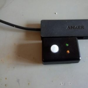
Then time to test: lets scavenge a super cheap reader microSD card reader:

And plug it: IT WORKS! After 3 min under the IR station, it does work.

I think I’ve to increase the pad size, in order to maximize the solder paste.

Now I’m confident sending to production, as I’ve quite a lot of theses cards in trays, ready for pick and place:

Simple CNC desktop router workflow and example

If you have access to a simple desktop mill/router, and you are not into mechanical part design, here is a very simple workflow:

Workflow

Sofware

You will only need free/open source program:

Example

In order to illustrate this example, we are going to make a case for a nice Nixie Clock from PV Electronics

A simple Ikea-hack will do for the wooden box: DRAGAN 2-piece bathroom dish set, bamboo

The front panel is milled

And fitted in place

The 2 stainless steel feet are from Ikea again

Thanks Dan Heeks for the very good software.

Happy milling!

Files are available here.

Dirt cheap DIY Smartphone Bike Mount

I use my bike quite a lot to commute in the city.

And, sometimes, to find the good street (believe me, in France, it’s not that easy) with the GPS while riding is tricky.

So I’ve been looking on the Internet to find THE good smartphone holder: unfortunately they are either bulky or expensive (and most of the time both)

Except this one: the Finn, a $9.95 silicone mount:

But buying things is not the hacker’s way.

So let’s take the design on Inkscape:

Download the pdf file here and print it on a A4 paper sheet without scaling.

Tape it with carpet double side tape on an old bike tube.

Cut the tube by cutting the paper pattern at the same time and remove the paper and tape.

Rub’it on your bike and let’s ride!

Important: the mount has to go on the back of the handle bar, as shown on the step 3.


XCSoar: generate custom maps

Introduction

XCSoar is an Open Source software for tactical glide computer: run it on any PDA/Smartphone/eBook and you have a powerfull computer for sailplane, paradlider and hang glider. (see previous post about adding a GPS to an eReader)

Generated map can be downloaded here

The geo file format used by XCSoar are:

  • elevation geotiff raster with altitude encoded (custom format)
  • waypoints
  • airspace
  • any shapefile

We will use the latest to add custom geo referenced information on XCSoar (in this case, paragliding skyways from thermal.kk7)

Software requirement

 Processing files

#remove and create temp folder for file processing
rm -rf tmp/; mkdir tmp/
#convert PNG+PGW to GeoTiff and resize for faster processing (resize to any % or none)
gdal_translate ./skyways_all.png tmp/skyways_all.tif -outsize 50% 50%
#vectorize contour to shapefile red layer
gdal_contour tmp/skyways_all.tif tmp/skyways_all_r.shp -i 50 -b 1
#vectorize contour to shapefile green layer
gdal_contour tmp/skyways_all.tif tmp/skyways_all_g.shp -i 80 -b 2
#vectorize contour to shapefile blue layer
gdal_contour tmp/skyways_all.tif tmp/skyways_all_b.shp -i 200 -b 3


Visualisation with QGIS

Import from Layer->Add Vector Layer and select your 3 files

Then if everything is fine, save the 3 as Shapefiles:

Place the generated file into the XCM (XCSoar compressed archive map)

Dont forget to edit the topology.tpl to add the names of the new files:

You can edit color (RGB, 0-255)  and transparency (0-255)

The order is important: element are displayed from top to bottom (first to last)

Result

Original raster file, PNG + PGW format.

Generated shapefile maps in XCSoar (desktop version)

Same in XCSoar but eReader version optimised for black and white gray levels.

Generated map can be downloaded here

USB motion sensor (PIR) to activate monitor

I have an always on net-book for weather forecast (yeah, when paragliding, you need the most up to date forecast)
It basically displays a full screen custom web-page with time and date and weather.

Its always on, not really good for the back-light and energy consumption.

So I got the idea of plugging a PIR sensor to wake up the screen when someone approach it.

Take an Arduino Micro Pro (4€ for the Chinese version), a PIR sensor (2€), a Hammond case (1€) and an USB A male from scrap (0€).

Let’s give a try, with a basic wiring, and this sketch to emulate keyboard thanks to it’s USB HID, the Arduino Micro Pro is a must.

Updated 05-01-2017:

  • code with USB wakeuphost and capslock instead of ctrl
  • green TX led always on
  • orange RX led only on motion
#include <Keyboard.h>

#define SENSOR_PIN 10   // Senor state input pin
#define RX_LED_PIN  17  // The RX LED has a defined Arduino pin
static bool sensor_previous_state = false;

void setup()
{
  pinMode(SENSOR_PIN, INPUT);  // PIR sensor pin as input
  pinMode(RX_LED_PIN, OUTPUT);     //  RX LED as an output
  digitalWrite(RX_LED_PIN, HIGH);  //  RX LED off
  TXLED0;                     // switch on TX green to show init/powered up (only available by macro)
  sensor_previous_state = digitalRead(SENSOR_PIN); // get sensor initial state (can be already true)
}

void loop()
{
  bool sensor_current_state = digitalRead(SENSOR_PIN);
  if ( sensor_previous_state == false   // looping until we detect a rising edge
       && sensor_current_state == true) {// when sensor state is trigged, it takes about 20 sec to recover
    digitalWrite(RX_LED_PIN, LOW);   // set the LED on
    USBDevice.wakeupHost();
    Keyboard.press( KEY_CAPS_LOCK );
    Keyboard.release( KEY_CAPS_LOCK );
    TXLED0;                     // great hackery in this: we have to force down the TXLED
    delay(1000);                  // wait a bit for the led
  } else {
    digitalWrite(RX_LED_PIN, HIGH);    // set the LED off
    TXLED0;
  }
  sensor_previous_state = sensor_current_state;
}
2017 update: lightguide for green and orange LEDs:
p70105-114417
Update: LED lightguides from the scrap box
And voila!
Quite nice, discrete and works very well, for about 10€/$.